CIA114F5, CIA111, CIA114 specifications
Extron Electronics is a renowned name in the AV control and distribution industry, and their products are designed to streamline and enhance audiovisual systems. Among their offerings are the CIA114F5, CIA111, and CIA114, each tailored to meet specific user needs while encapsulating cutting-edge technology and features.The CIA114F5 is a high-performance, five-channel amplifier designed for distributed audio applications. One of its standout features is its ability to deliver 30 watts per channel, allowing for exceptional audio clarity and power across multiple zones. The amplifier utilizes Extron's patented Class D output technology, ensuring high efficiency and reduced heat generation, which translates to a longer lifespan and lower operational costs. The CIA114F5 also includes built-in signal processing capabilities, such as equalization and filtering, which help optimize audio performance in various environments.
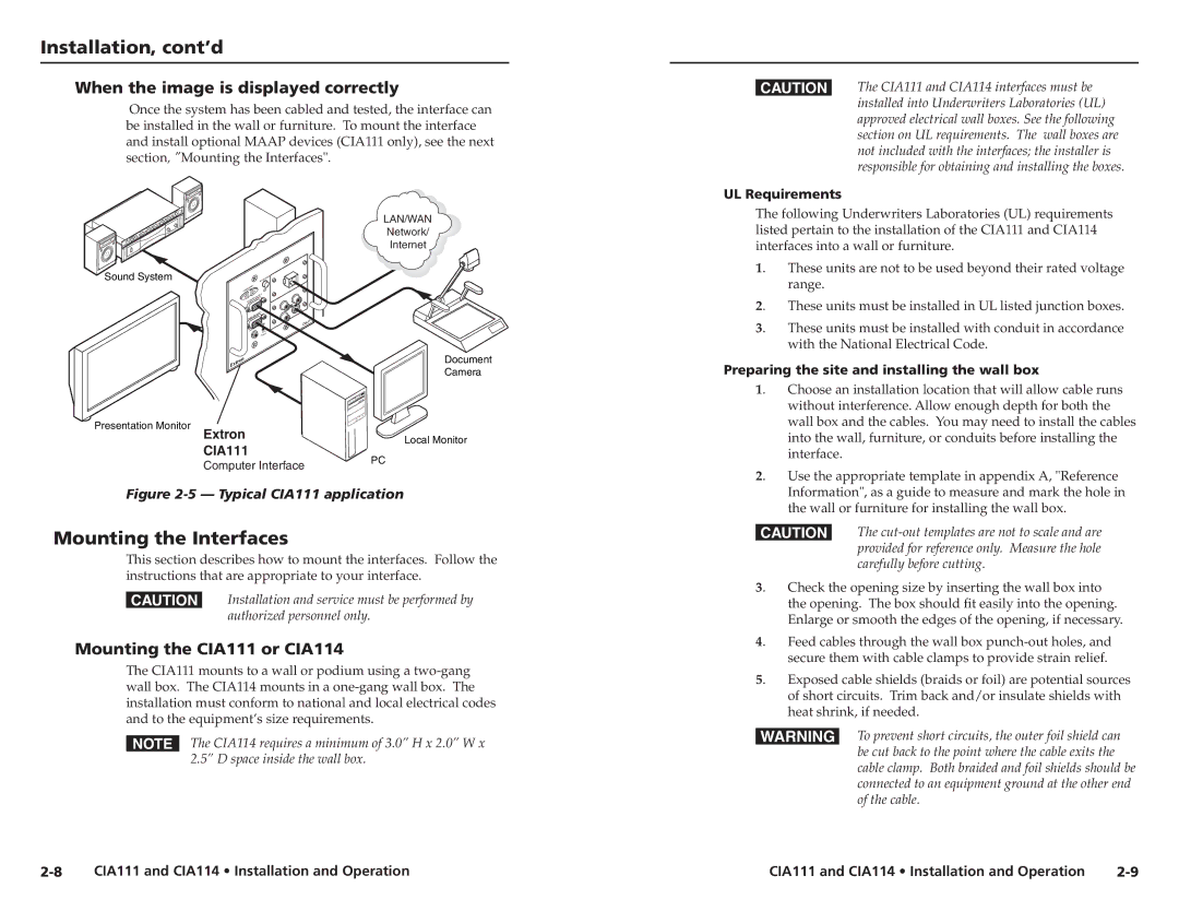
Moving to the CIA111, this model is a compact, single-channel amplifier, perfect for smaller setups or individual zones in larger systems. It provides 25 watts of power, making it suitable for classrooms, conference rooms, and similar venues where clarity in sound is paramount. The CIA111 features a highly efficient design and is equipped with Extron's exclusive Energy Saver technology, which minimizes power consumption when the amplifier is not in use. This not only extends the product's life but also has a positive impact on overall energy costs.
Lastly, the CIA114 is another versatile component that provides four output channels, each capable of delivering 30 watts. This model stands out with its versatile installation options, which include mounting on a rack or against a wall. The CIA114 uses advanced circuit design to minimize distortion and provide a rich sound stage, enhancing the listening experience in various applications. Additionally, its compatibility with Extron's control systems allows for seamless integration into existing AV setups, empowering users with effortless control over audio distribution.
In summary, Extron's CIA114F5, CIA111, and CIA114 amplifiers represent the pinnacle of reliability and performance in distributed audio systems. With features like class D amplification, built-in processing, and energy-saving technologies, these models cater to a broad range of AV needs, ensuring that users receive the best possible audio experience in any environment.

