Installation and Operation, cont’d
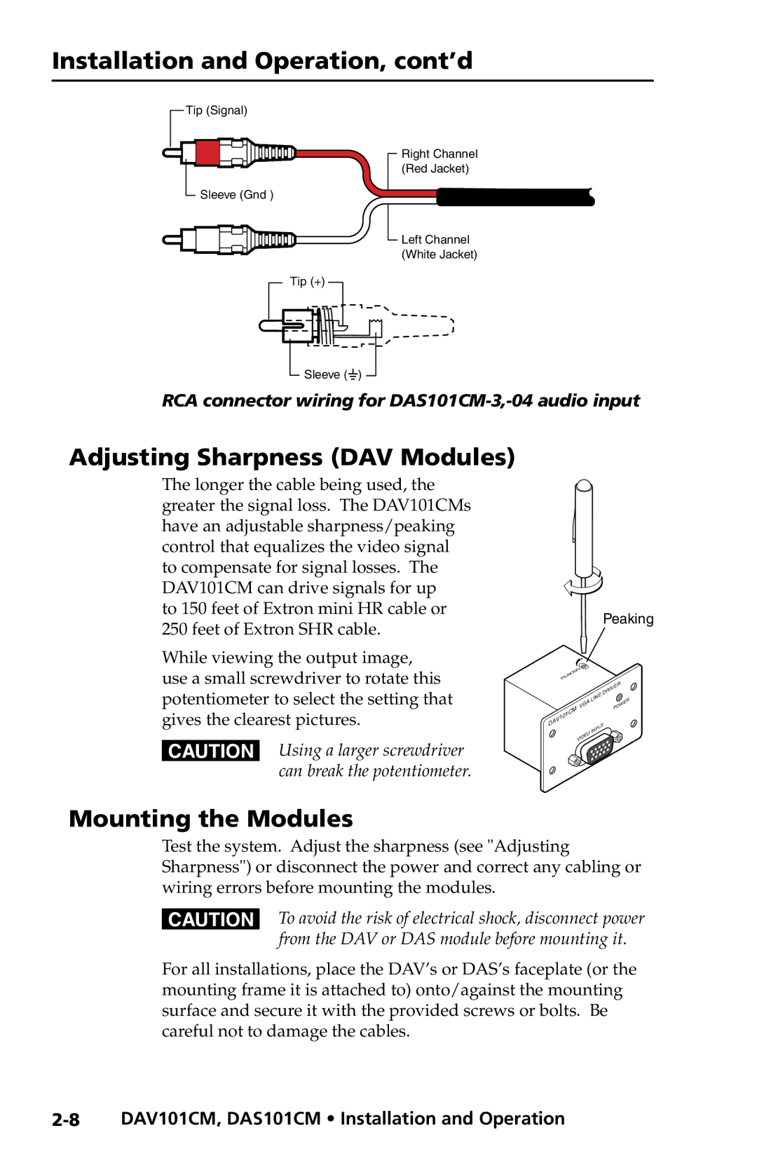
Tip (Signal)
![]() Sleeve (Gnd )
Sleeve (Gnd )
Tip (+)
![]() Sleeve (
Sleeve (![]() )
)
Right Channel (Red Jacket)
![]() Left Channel (White Jacket)
Left Channel (White Jacket)
RCA connector wiring for
Adjusting Sharpness (DAV Modules)
The longer the cable being used, the greater the signal loss. The DAV101CMs have an adjustable sharpness/peaking control that equalizes the video signal to compensate for signal losses. The DAV101CM can drive signals for up
to 150 feet of Extron mini HR cable or 250 feet of Extron SHR cable.
While viewing the output image, use a small screwdriver to rotate this potentiometer to select the setting that gives the clearest pictures.
CUsing a larger screwdriver can break the potentiometer.
Peaking
|
|
|
|
|
| ING |
|
|
|
|
|
|
| |
|
|
|
|
| K |
|
|
|
|
|
|
|
| |
|
|
|
| A |
|
|
|
|
|
|
|
|
| |
|
|
| E |
|
|
|
|
|
|
|
|
|
| |
|
| P |
|
|
|
|
|
|
|
|
|
|
| |
|
|
|
|
|
|
|
|
|
|
|
| DRIVER |
| |
|
|
|
|
|
|
|
|
|
| LINE |
| W | ER | |
|
|
|
|
|
|
| VGA |
|
| PO | ||||
|
|
| 01C | M |
|
|
|
| ||||||
|
|
|
|
|
|
|
|
|
|
| ||||
| A | V1 |
|
|
|
|
|
|
|
|
| |||
D |
|
|
|
|
|
|
|
|
| T |
|
| ||
|
|
|
|
|
|
|
|
| PU |
|
| |||
|
|
|
|
|
|
|
|
| IN |
|
| |||
|
|
|
|
|
|
|
|
| O |
|
|
| ||
|
|
|
|
|
|
|
| DE |
|
|
|
| ||
|
|
|
|
|
|
| VI |
|
|
|
|
| ||
|
|
|
|
|
|
|
|
|
|
|
|
| ||
|
|
|
|
|
|
|
|
|
|
|
|
|
| |
Mounting the Modules
Test the system. Adjust the sharpness (see "Adjusting Sharpness") or disconnect the power and correct any cabling or wiring errors before mounting the modules.
CTo avoid the risk of electrical shock, disconnect power from the DAV or DAS module before mounting it.
For all installations, place the DAV’s or DAS’s faceplate (or the mounting frame it is attached to) onto/against the mounting surface and secure it with the provided screws or bolts. Be careful not to damage the cables.
