B | LC Jacks — Four fiber optic cables connect the transmitter to the | |
| receiver. The cables connect to the four female LC jacks in each | |
| of the units. |
|
| A label on the top panel identifies the unit as the transmitter | |
| or receiver and identifies the fiber optic port numbers and the | |
| power input. | |
| N For the transmitter, port 1 is closest to the power input | |
|
| and port 4 is furthest away. For the receiver, the ports |
|
| are in the reverse orientation: port 4 is closest to the |
|
| power input and port 1 is furthest away. |
|
| Although the orientation is reversed, ports with the |
|
| same number must be connected by the same cable, so |
|
| that port 1 on the receiver is connected to port 1 on the |
|
| transmitter, etc. |
| Insert the end of the fiber optic cable into the appropriate plug | |
| on the transmitter or receiver. The locking catch should snap | |
| into the slot and hold the cable securely in place. | |
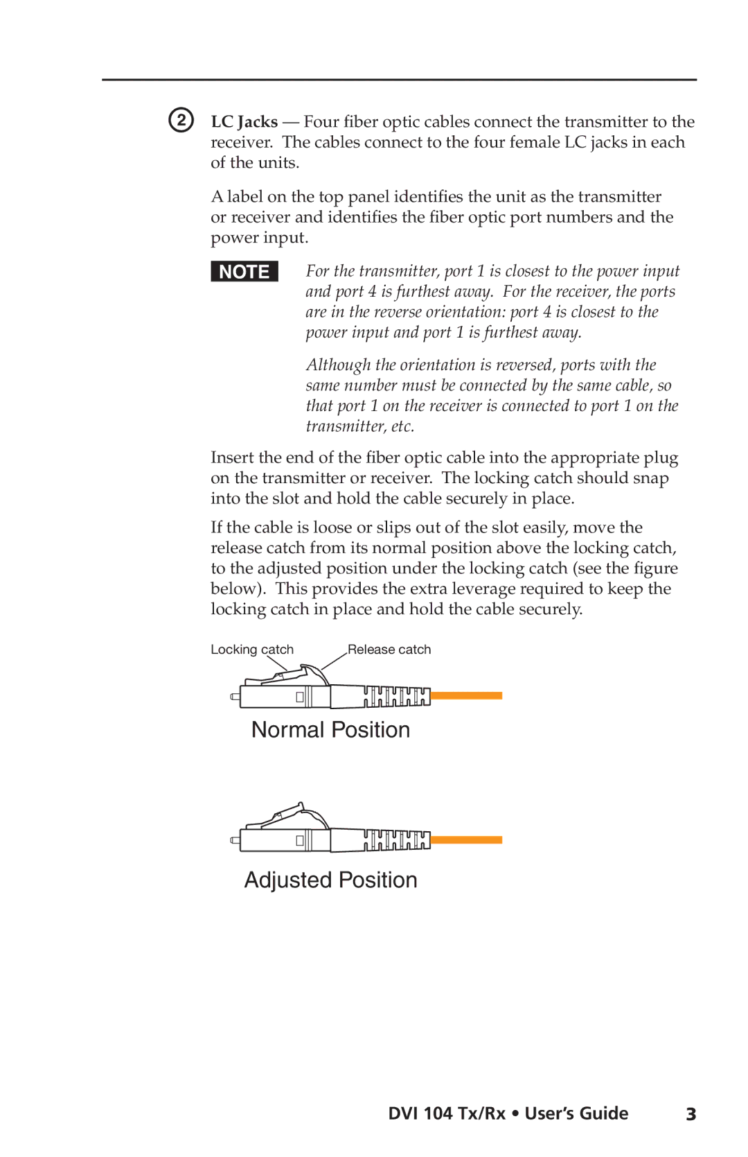
| If the cable is loose or slips out of the slot easily, move the | |
| release catch from its normal position above the locking catch, | |
| to the adjusted position under the locking catch (see the figure | |
| below). This provides the extra leverage required to keep the | |
| locking catch in place and hold the cable securely. | |
| Locking catch | Release catch |
Normal Position
Adjusted Position
DVI 104 Tx/Rx • User’s Guide | 3 |