Receiver Rear Panel Features
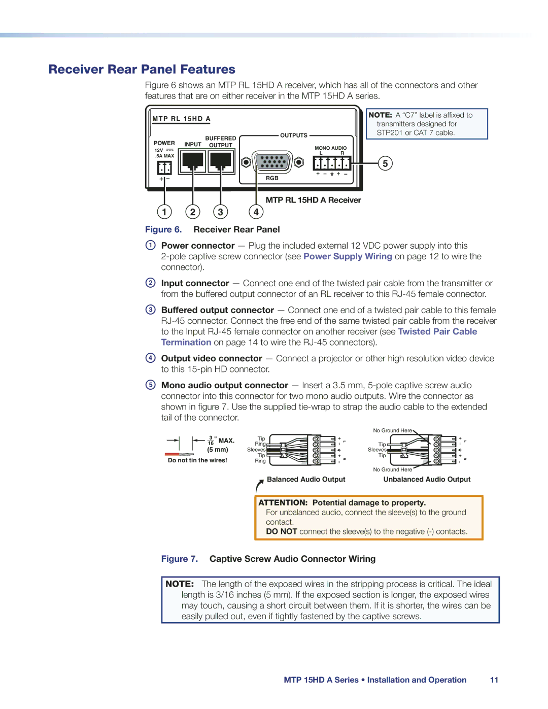
Figure 6 shows an MTP RL 15HD A receiver, which has all of the connectors and other features that are on either receiver in the MTP 15HD A series.
MTP RL 15HD A
| BUFFERED | OUTPUTS |
|
POWER |
|
| |
INPUT OUTPUT | MONO AUDIO | ||
12V |
| ||
| L | R | |
.5A MAX |
| ||
|
|
| |
RGB
NOTE: A “C7” label is affixed to transmitters designed for STP201 or CAT 7 cable.
5
MTP RL 15HD A Receiver
1 2 3 4
Figure 6. Receiver Rear Panel
APower connector — Plug the included external 12 VDC power supply into this
BInput connector — Connect one end of the twisted pair cable from the transmitter or from the buffered output connector of an RL receiver to this
CBuffered output connector — Connect one end of a twisted pair cable to this female
DOutput video connector — Connect a projector or other high resolution video device to this
EMono audio output connector — Insert a 3.5 mm,
No Ground Here
| Tip |
| Ring |
| Sleeves |
Do not tin the wires! | Tip |
Ring |
L | Tip | L |
|
| |
| Sleeves |
|
R | Tip | R |
| ||
| No Ground Here |
|
Balanced Audio Output | Unbalanced Audio Output |
ATTENTION: Potential damage to property.
For unbalanced audio, connect the sleeve(s) to the ground contact.
DO NOT connect the sleeve(s) to the negative
Figure 7. Captive Screw Audio Connector Wiring
NOTE: The length of the exposed wires in the stripping process is critical. The ideal length is 3/16 inches (5 mm). If the exposed section is longer, the exposed wires may touch, causing a short circuit between them. If it is shorter, the wires can be easily pulled out, even if tightly fastened by the captive screws.
MTP 15HD A Series • Installation and Operation | 11 |