Power Supply Wiring and Grounding
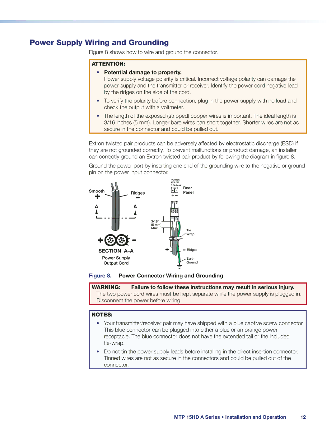
Figure 8 shows how to wire and ground the connector.
ATTENTION:
•Potential damage to property.
Power supply voltage polarity is critical. Incorrect voltage polarity can damage the power supply and the transmitter or receiver. Identify the power cord negative lead by the ridges on the side of the cord.
•To verify the polarity before connection, plug in the power supply with no load and check the output with a voltmeter.
•The length of the exposed (stripped) copper wires is important. The ideal length is 3/16 inches (5 mm). Longer bare wires can short together. Shorter wires are not as secure in the connector and could be pulled out.
Extron twisted pair products can be adversely affected by electrostatic discharge (ESD) if they are not grounded correctly. To prevent malfunctions or product damage, an installer can correctly ground an Extron twisted pair product by following the diagram in figure 8.
Ground the power port by inserting one end of the grounding wire to the negative or ground pin on the power input connector.
| POWER |
| |
| 12V |
| |
Smooth | 0.5A MAX | Rear | |
Ridges | Panel | ||
| |||
A | A |
|
3/16" ![]() (5 mm)
(5 mm)
Max. ![]()
![]()
![]() Tie
Tie ![]() Wrap
Wrap
SECTION
Power Supply
Output Cord
![]() Ridges
Ridges
Earth
Ground
Figure 8. Power Connector Wiring and Grounding
WARNING: Failure to follow these instructions may result in serious injury. The two power cord wires must be kept separate while the power supply is plugged in. Disconnect the power before wiring.
NOTES:
•Your transmitter/receiver pair may have shipped with a blue captive screw connector. This blue connector can be plugged into either a blue or an orange power receptacle. The blue connector does not have the extended tail or the included
•Do not tin the power supply leads before installing in the direct insertion connector. Tinned wires are not as secure in the connectors and could be pulled out of the connector.
MTP 15HD A Series • Installation and Operation | 12 |