Transmitter Rear Panel Features
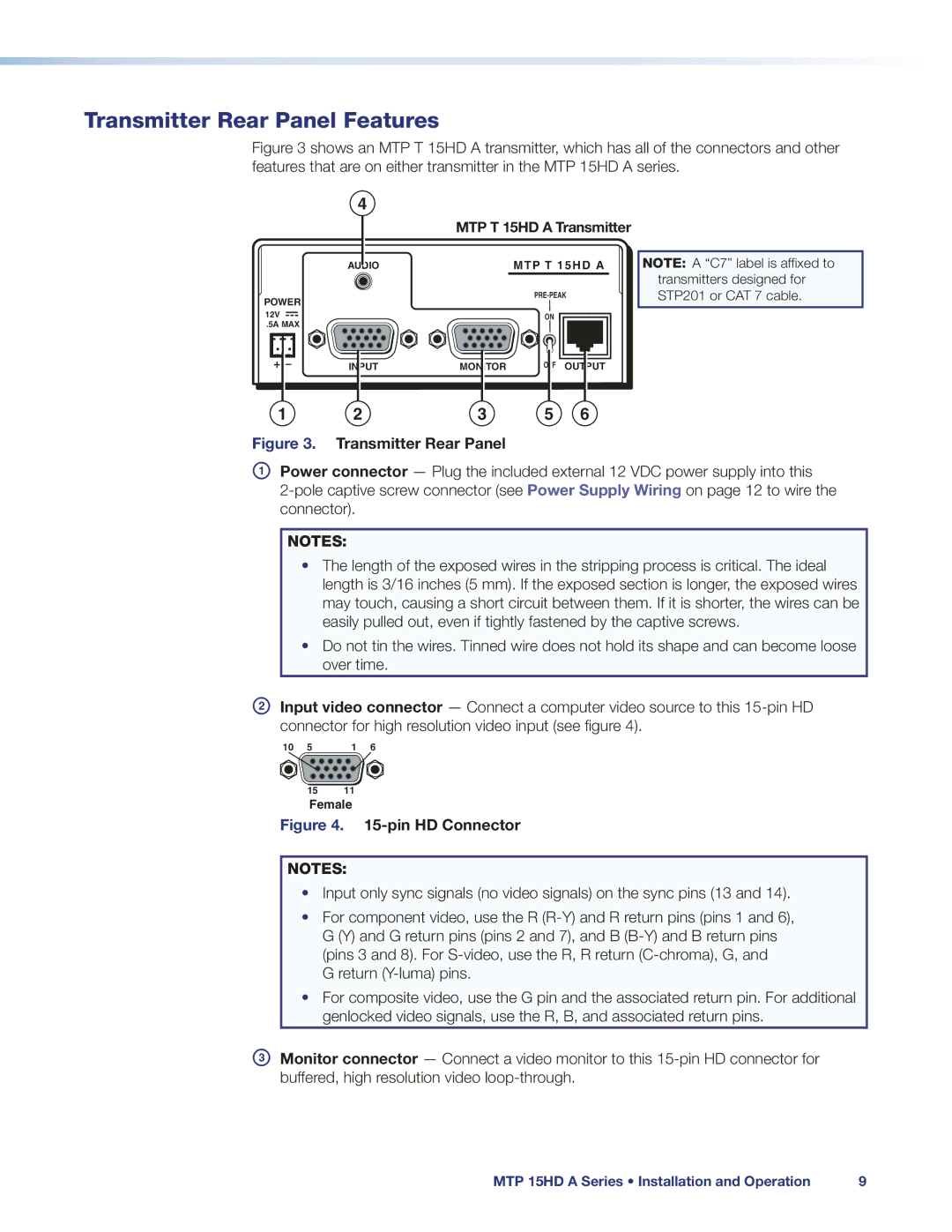
Figure 3 shows an MTP T 15HD A transmitter, which has all of the connectors and other features that are on either transmitter in the MTP 15HD A series.
4
MTP T 15HD A Transmitter
| AUDIO |
| MTP T 15HD A | |
POWER |
|
| ||
|
|
|
| |
12V |
|
| ON |
|
.5A MAX |
|
|
|
|
| INPUT | MONITOR | OFF | OUTPUT |
1 | 2 | 3 | 5 | 6 |
NOTE: A “C7” label is affixed to transmitters designed for STP201 or CAT 7 cable.
Figure 3. Transmitter Rear Panel
APower connector — Plug the included external 12 VDC power supply into this
NOTES:
•The length of the exposed wires in the stripping process is critical. The ideal length is 3/16 inches (5 mm). If the exposed section is longer, the exposed wires may touch, causing a short circuit between them. If it is shorter, the wires can be easily pulled out, even if tightly fastened by the captive screws.
•Do not tin the wires. Tinned wire does not hold its shape and can become loose over time.
BInput video connector — Connect a computer video source to this
10 | 5 | 1 | 6 |
15 11
Female
Figure 4. 15-pin HD Connector
NOTES:
•Input only sync signals (no video signals) on the sync pins (13 and 14).
•For component video, use the R
G return
•For composite video, use the G pin and the associated return pin. For additional genlocked video signals, use the R, B, and associated return pins.
CMonitor connector — Connect a video monitor to this
MTP 15HD A Series • Installation and Operation | 9 |
