PS 124, cont’d
Output power — wiring the DC output connectors
The PS 124 can supply 12 VDC to multiple devices using
3.5mm,
NTo verify proper polarity before connection to a device, plug in the power supply with no load and check the output polarity with a voltmeter. Remove power before continuing.
WWhen verifying power supply polarity, the two power cord wires must be kept separate while the power supply is plugged in.
To connect products to the outputs of the PS 124:
1. Cut the DC output cord to the length required.
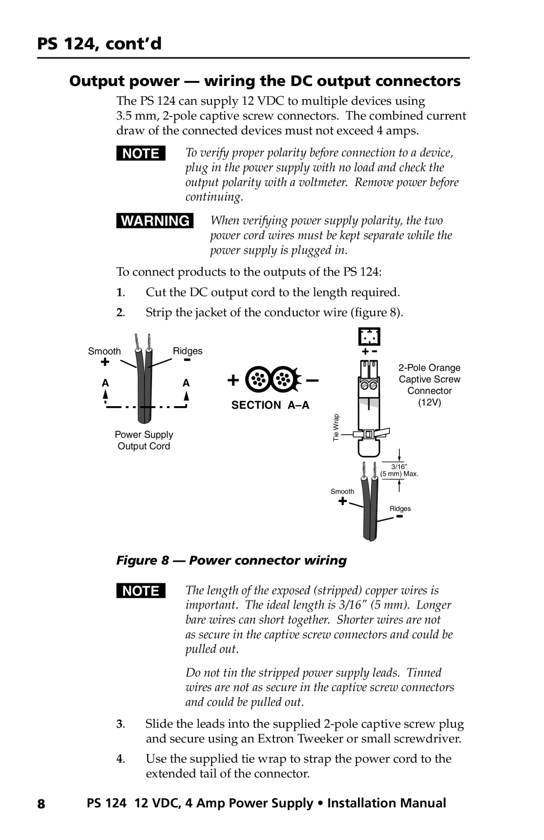
2. Strip the jacket of the conductor wire (figure 8).
Smooth | Ridges |
A | A |
Power Supply
Output Cord
+ ![]()
![]()
![]()
![]() –
–
SECTION
Tie Wrap![]()
![]()
![]()
Captive Screw
Connector
(12V)
3/16”
(5 mm) Max.
Smooth
Ridges
Figure 8 — Power connector wiring
NThe length of the exposed (stripped) copper wires is important. The ideal length is 3/16" (5 mm). Longer bare wires can short together. Shorter wires are not as secure in the captive screw connectors and could be pulled out.
Do not tin the stripped power supply leads. Tinned wires are not as secure in the captive screw connectors and could be pulled out.
3. Slide the leads into the supplied
4. Use the supplied tie wrap to strap the power cord to the extended tail of the connector.
8 PS 124 12 VDC, 4 Amp Power Supply • Installation Manual