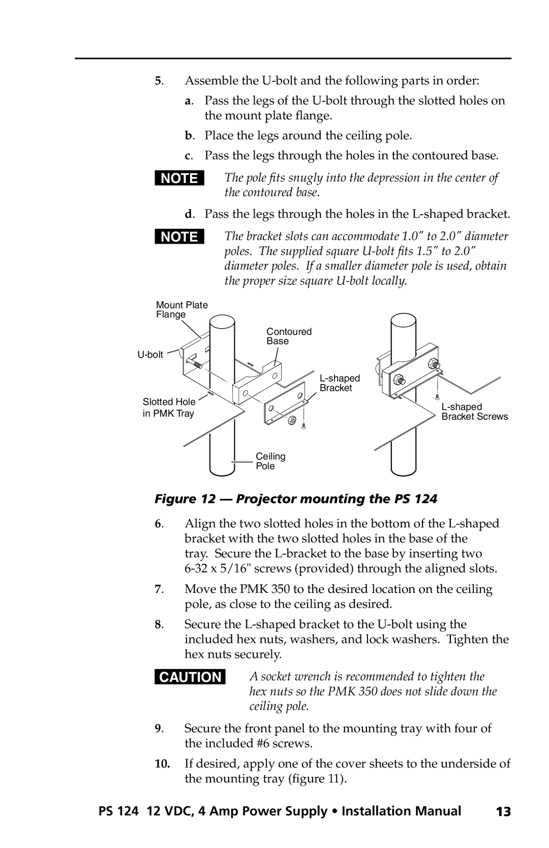
5. Assemble the
a. Pass the legs of the
b. Place the legs around the ceiling pole.
c. Pass the legs through the holes in the contoured base.
NThe pole fits snugly into the depression in the center of the contoured base.
d. Pass the legs through the holes in the L-shaped bracket.
NThe bracket slots can accommodate 1.0" to 2.0" diameter poles. The supplied square
Mount Plate
Flange
Contoured
Base
![]()
![]()
Slotted Hole | ||
in PMK Tray | ||
Bracket Screws | ||
|
Ceiling
![]() Pole
Pole
Figure 12 — Projector mounting the PS 124
6. Align the two slotted holes in the bottom of the
7. Move the PMK 350 to the desired location on the ceiling pole, as close to the ceiling as desired.
8. Secure the
CA socket wrench is recommended to tighten the hex nuts so the PMK 350 does not slide down the ceiling pole.
9. Secure the front panel to the mounting tray with four of the included #6 screws.
10.If desired, apply one of the cover sheets to the underside of the mounting tray (figure 11).
PS 124 12 VDC, 4 Amp Power Supply • Installation Manual | 13 |
