68-468-02 Printed in the USA
RGB 500 AKM RGB 560 AKM
Architectural Series Universal Interfaces with Audio and ADSP
Consignes de Sécurité Français
Precautions
Safety Instructions English
Sicherheitsanleitungen Deutsch
Table of Contents
RGB 500 AKM and RGB 560 AKM Table of Contents
Table of Contents, cont’d
ii RGB 500 AKM and RGB 560 AKM Table of Contents
Introduction
About the Interfaces Features
Chapter1One
RGB 500 AKM and RGB 560 AKM
Introduction
Features
RGB 500 AKM and RGB 560 AKM features
About the Interfaces
RGB 500 AKM and RGB 560 AKM Introduction
RGB 500 AKM feature
RGB 560 AKM features
Introduction, cont’d
1-4 RGB 500 AKM and RGB 560 AKM Introduction
Installation and Operation Instructions
Installation and Operation
Front Panel Features Installation Overview
Chapter2Two
2-2 RGB 500 AKM and RGB 560 AKM Installation and Operation
Installation and Operation
Front Panel Features
Figure 2 - RGB 500 AKM front panel
right, control sync on green, sync processing, serration
eight DIP switches, numbered 1 through 8 from left to
RGB 500 AKM and RGB 560 AKM Installation and Operation
pulse, composite sync output , force negative sync
Computer video input 15-pin HD female connector RGB 560 AKM only
Installation and Operation, cont’d
Computer video input 9-pin D male connector RGB 500 AKM only
10 Front panel DIP switches RGB 560 AKM only
Adjusting the gain/peaking jumpers
Installation Overview
Installation and Operation Instructions
Audio output connector
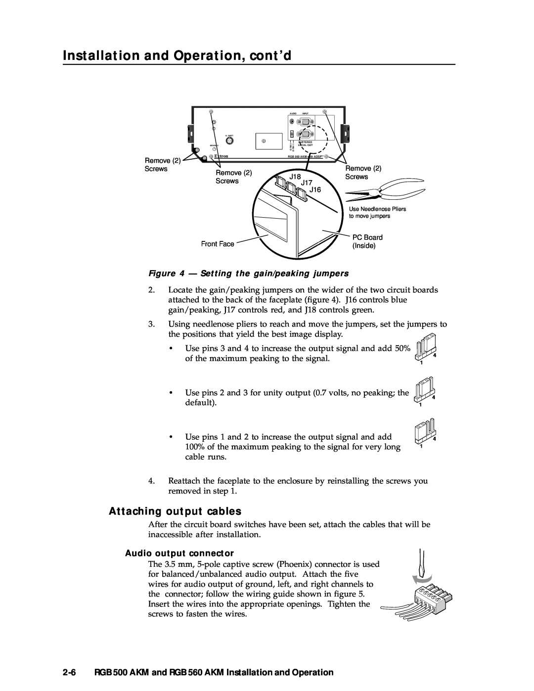
Figure 4 - Setting the gain/peaking jumpers
of the maximum peaking to the signal
2-6 RGB 500 AKM and RGB 560 AKM Installation and Operation
Figure 5 - Wiring for audio output
Connecting input cables
Pre-installation testing/troubleshooting
Power connector
2-8 RGB 500 AKM and RGB 560 AKM Installation and Operation
Figure 6 - Typical RGB 500 AKM and RGB 560 AKM applications
Specifications
AAppendix A
Video
Specifications
A-2 RGB 500 AKM and RGB 560 AKM Specifications
Video input
Audio output
RGB 500 AKM and RGB 560 AKM Specifications A-3
Audio input
General
Specifications, cont’d
A-4 RGB 500 AKM and RGB 560 AKM Specifications
Part Numbers
Interfaces Cables Other Accessories
AppendixBB
Cables
Part Numbers
Interfaces
RGB 500 AKM
RGB 500 AKM and RGB 560 AKM
Other Accessories
High-resolution cables
Adapter laptop breakout cables Part number
Part Numbers, cont’d
B-4 RGB 500 AKM and RGB 560 AKM Part Numbers
and Central America
USA, Canada, South America
Europe, Africa, and
the Middle East