Installation and Operation, cont’d
Audio input connections
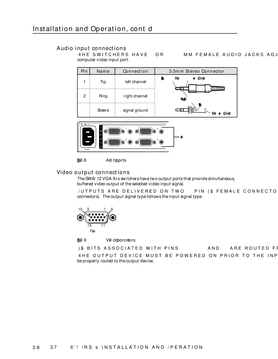
The switchers have 8 or 12 3.5mm female audio jacks adjacent to the corresponding
computer video input port.
Pin | Name | Connection | 3.5mm Stereo Connector | |
1 | Tip | left channel | Tip (L+) | Sleeve (Gnd) |
|
| |||
2 | Ring | right channel |
| Ring (R+) |
|
|
|
| |
|
|
|
| Tip (L+) |
3 | Sleeve | signal ground |
| Sleeve (Gnd) |
|
|
|
| |
50/60Hz |
|
|
| |
| I | 1 | 3 |
|
| N |
| ||
|
|
|
| |
P |
| Audio input ports |
U |
| |
2 | 4 | |
T |
|
|
S |
|
|
1.2A MAX
Figure 2-8 — Audio input ports
Video output connections
The SW8/12 VGA Ars switchers have two output ports that provide simultaneous, buffered video output of the selected video input signal.
Outputs are delivered on two
10 | 5 | 1 | 6 |
1511
Female
Figure 2-9 — Video output connectors
ID bits associated with pins 4, 11, 12, and 15 are routed from the input 1 to output 1.
The output device must be powered on prior to the input device for the ID bits to be properly routed to the output device.