Installation and Operartion, cont’d

L 1 R L 2 R L 3 R L 4 R L 5 R L 6 R L 1 R

4

5

6

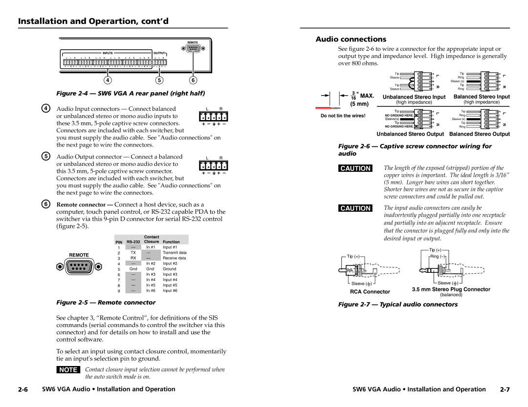
Figure 2-4 — SW6 VGA A rear panel (right half)

D

Audio Input connectors — Connect balanced


or unbalanced stereo or mono audio inputs to


these 3.5 mm, 5-pole captive screw connectors.


Connectors are included with each switcher, but


you must supply the audio cable. See "Audio connections" on


the next page to wire the connectors.

E

Audio Output connector — Connect a balanced


or unbalanced stereo or mono audio device to


this 3.5 mm, 5-pole captive screw connector.


Connectors are included with each switcher, but


you must supply the audio cable. See "Audio connections" on


the next page to wire the connectors.

F

Remote connector — Connect a host device, such as a


computer, touch panel control, or RS-232 capable PDA to the


switcher via this 9-pin D connector for serial RS-232 control


(figure 2-5).


Contact


PIN

RS-232

Closure

Function


1

In #1

Input #1

REMOTE

2

TX

Transmit data

3

RX

Receive data


4

In #2

Input #2


5

Gnd

Gnd

Ground


6

In #3

Input #3


7

In #4

Input #4


8

In #5

Input #5


9

In #6

Input #6

Figure 2-5 — Remote connector

See chapter 3, “Remote Control”, for definitions of the SIS commands (serial commands to control the switcher via this connector) and for details on how to install and use the control software.

To select an input using contact closure control, momentarily tie an input's selection pin to ground.

NContact closure input selection cannot be performed when the auto switch mode is on.

Audio connections

See figure 2-6 to wire a connector for the appropriate input or output type and impedance level. High impedance is generally over 800 ohms.

Tip

L

Tip

L

Sleeve

Ring


Sleeve (s)


Tip

R

Tip

R

Sleeve

Ring


Unbalanced Stereo Input

Balanced Stereo Input


(high impedance)


(high impedance)


Do not tin the wires!

Tip

L

Tip

L

NO GROUND HERE.

Ring


Sleeve(s)


Sleeve (s)


Tip

R

Tip

R


NO GROUND HERE.

Ring


Unbalanced Stereo Output

Balanced Stereo Output

Figure 2-6 — Captive screw connector wiring for audio

CThe length of the exposed (stripped) portion of the copper wires is important. The ideal length is 3/16” (5 mm). Longer bare wires can short together. Shorter bare wires are not as secure in the captive screw connectors and could be pulled out.

CThe input audio connectors can easily be inadvertently plugged partially into one receptacle and partially into an adjacent receptacle. Ensure that the connector is plugged fully and only into the desired input or output.


Tip (+)

Tip (+)

Ring (-)

Sleeve ( )

Sleeve ( )

RCA Connector

3.5 mm Stereo Plug Connector

(balanced)


Figure 2-7 — Typical audio connectors

2-6

SW6 VGA Audio • Installation and Operation

SW6 VGA Audio • Installation and Operation

2-7

Page 9
Image 9
Extron electronic SW6 user manual Audio connections, Balanced Stereo Input

SW6 specifications

Extron Electronics is renowned for its innovative solutions in the audiovisual (AV) industry. Among its extensive range of products, the SW6 and SW8 series stand out as versatile audio/video switchers designed to streamline the process of managing multiple AV sources.

The Extron SW6 and SW8 are classified as standalone switchers that cater to various application needs, making them particularly suitable for classrooms, conference rooms, and control rooms. The SW6 model allows for the switching of up to six AV sources, while the SW8 model expands this capability to eight sources. This flexibility is crucial in environments where multiple devices need to be connected seamlessly, enhancing productivity and collaboration.

One of the main features of the SW6 and SW8 switchers is their input versatility. They can accommodate a wide array of video formats, including HDMI, VGA, and composite video, ensuring compatibility with older and newer devices alike. Furthermore, both models support audio formats, allowing for the integration of both video and sound sources in a single unit. The switchers typically include audio embedding, which seamlessly combines audio from a chosen source with the video output, enabling streamlined audio and video transmission.

In terms of technology, the Extron SW6 and SW8 devices incorporate advanced switching technology that ensures reliable signal management with minimal latency. Setting them apart is their ability to support features like automatic input switching, allowing users to enjoy an uninterrupted viewing experience without the need for manual intervention. The included RS-232 and Ethernet control capabilities also provide flexibility for integration into larger control systems, enhancing their functionality within complex AV setups.

Additionally, both the SW6 and SW8 series are designed with user-friendly interfaces. Front-panel push buttons allow for intuitive operation, while remote control options give flexibility for integration into existing systems. The units also feature status indicators, providing users with real-time feedback on the currently selected input, making operation straightforward even for non-technical users.

In conclusion, the Extron SW6 and SW8 audio/video switchers are essential tools for managing multiple AV sources with ease. Their versatility in handling various input formats, advanced switching technology, and user-friendly design make them ideal for a range of applications. Whether in an educational setting or a corporate environment, these switchers deliver superior performance and reliability, affirming Extron’s commitment to excellence in the audiovisual landscape.