Installation and Operation, cont’d
3. | Affix the supplied rubber pad to the side of the |
| clamping plate that the projector pole contacts. |
4. | Place the |
| legs of the |
| mounting plate, then through the round holes on the |
| backing brace. |
| • For a typical (1.5" to 2.0" diameter) pole — You can use |
| the supplied square |
| pole. |
| • For a smaller or larger pole — Locally obtain a square |
| |
| the bracket can accommodate a square |
| sizes from 1.0" to 2.5" in diameter. |
5. | Secure the bracket to the |
| nuts, washers, and lock washers. Tighten the hex nuts just |
| enough that they can be loosened by hand. |
Using the PMK 350 Projector Mount Kit
The PMK 350 Low Profile Projector Mount Kit is an above- projector mounting kit that attaches to a 1" to 2" diameter projector mounting pole. It can hold more than one device, in a variety of sizes. The PMK 350 is available in black (part
Follow these steps to mount the YCS 100 on the PMK 350 bracket as follows:
1. | Remove the front and back panels from the |
| PMK 350, using an Extron Tweeker or other small Philips |
| screwdriver. (Retain the screws to reattach the plates when |
| you are finished.) |
2. | Remove any rubber feet from the bottom of the YCS 100. |
3. | Secure the YCS to one side of the mounting bracket, |
| using two of the supplied |
| (diagonal) corners. |
4. | Using the two included tie wraps, strap the YCS power |
| supply to the PMK 350 bracket. |
5.Place the bracket around the projector ceiling mounting pole as shown in figure
6. | Place the rubberized contoured base against the pole and |
| opposite the back plate. The pole should fit snugly into the |
| depression in the center of the contoured base. |
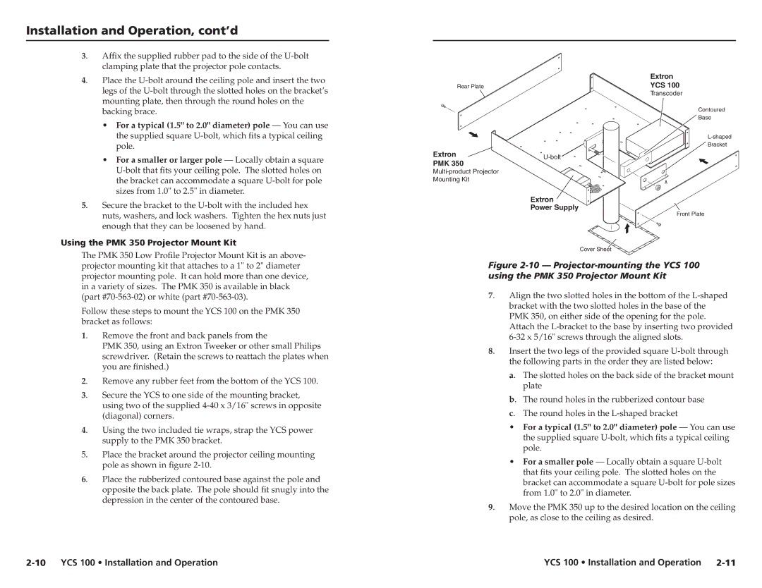
| Extron | |
Rear Plate | YCS 100 | |
| Transcoder | |
| Contoured | |
| Base | |
| ||
| Bracket | |
Extron | ||
PMK 350 | ||
|
Mounting Kit
Extron
Power Supply
Front Plate
Cover Sheet
Figure 2-10 — Projector-mounting the YCS 100 using the PMK 350 Projector Mount Kit
7. | Align the two slotted holes in the bottom of the | |
| bracket with the two slotted holes in the base of the | |
| PMK 350, on either side of the opening for the pole. | |
| Attach the | |
| ||
8. | Insert the two legs of the provided square | |
| the following parts in the order they are listed below: | |
| a. | The slotted holes on the back side of the bracket mount |
|
| plate |
| b. | The round holes in the rubberized contour base |
| c. | The round holes in the |
| • | For a typical (1.5" to 2.0" diameter) pole — You can use |
|
| the supplied square |
|
| pole. |
| • | For a smaller pole — Locally obtain a square |
|
| that fits your ceiling pole. The slotted holes on the |
|
| bracket can accommodate a square |
|
| from 1.0" to 2.0" in diameter. |
9. | Move the PMK 350 up to the desired location on the ceiling | |
| pole, as close to the ceiling as desired. | |
| YCS 100 • Installation and Operation |