Installation and Operation, cont’d
10. Secure the
NBe sure to tighten the hex nuts securely enough that the PMK 350 does not slide down the ceiling pole. A socket wrench is recommended to tighten the hex nuts.
11. Secure the front panel to the mounting tray with four of the included #6 screws.
12. If desired, choose one of the provided four sizes of self- adhesive cover sheets, and apply it to the underside of the mounting tray.
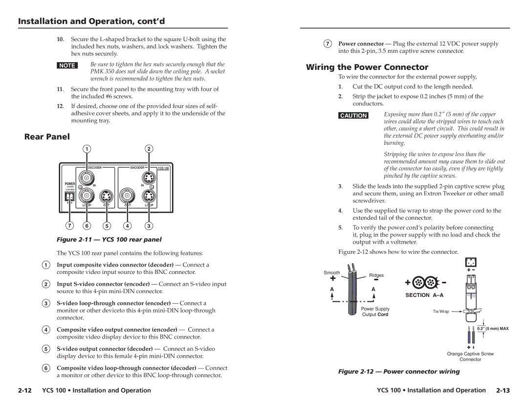
Rear Panel
| 1 |
|
| 2 |
| DECODER |
| ENCODER | YCS 100 |
12V | IN |
| IN |
|
|
|
|
| |
0.3A MAX |
|
|
|
|
| LOOP | OUT | OUT | LOOP |
7 6 5 4 3
Figure 2-11 — YCS 100 rear panel
The YCS 100 rear panel contains the following features:
1Input composite video connector (decoder) — Connect a composite video input source to this BNC connector.
2Input
3
4Composite video output connector (encoder) — Connect a composite video display device to this BNC connector.
5
6Composite video
7Power connector — Plug the external 12 VDC power supply into this
Wiring the Power Connector
To wire the connector for the external power supply,
1. | Cut the DC output cord to the length needed. |
2. | Strip the jacket to expose 0.2 inches (5 mm) of the |
| conductors. |
CExposing more than 0.2" (5 mm) of the copper wires could allow the stripped wires to touch each other, causing a short circuit. This could result in the external DC power supply overheating and/or burning.
Stripping the wires to expose less than the recommended amount may cause them to slide out of the connector too easily, even if they are tightly pinched by the captive screws.
3. | Slide the leads into the supplied |
| and secure them, using an Extron Tweeker or other small |
| screwdriver. |
4. | Use the supplied tie wrap to strap the power cord to the |
| extended tail of the connector. |
5. | To verify the power cord’s polarity before connecting |
| it, plug in the power supply with no load and check the |
| output with a voltmeter. |
Figure 2-12 shows how to wire the connector.
SmoothRidges
A | A | SECTION |
|
| |
| Power Supply | Tie Wrap |
| Output Cord | |
|
|
0.2” (5 mm) MAX
Orange Captive Screw
Connector
Figure 2-12 — Power connector wiring
| YCS 100 • Installation and Operation |