MODEL F80A
IMPORTANT: THIS FURNACE IS NOT TO BE VENTED IN THE SAME CHIMNEY OR VENTING SYSTEM SERVING A SOLID FUEL APPLIANCE (WOOD OR COAL). IF THE FURNACE IS TO BE VENTED INTO A CHIMNEY THAT NO LONGER SERVES A FIREPLACE, THE FIREPLACE OPENING IS TO BE PERMANENTLY SEALED.
The furnace must connect to a listed chimney (B-1 Vent), or vent complying with a recognized standard, or a suitably sized, constructed and lined masonry chimney. The chimney lining method and material must comply with local requirements. Use corrosion resistant material meeting nationally recognized standards for vent construction.
Avoid over sizing the furnace for the application. A furnace selected as close as possible for the actual building heat loss will have longer firing cycles which will reduce the potential for damaging condensate formation in the venting system.
Take the building orientation and the presence of other buildings or other nearby structures into consideration when planning the venting system location. Certain external structures could create air turbulence around the vent termination leading to downdrafts and similar venting problems.
If local experience indicates that condensation problems are probable, provide for drainage and disposal of venting system condensate.
VENT SIZING
The venting system, taking all appliances to be vented into consideration, must be sized in accordance with the Venting Tables and rules published in the current editions of ANSI Z223.1 / NFPA 54, National Fuel Gas Code in the United States, or B149, Natural Gas and Propane Installation Code in Canada. An undersized venting system will not permit the complete removal of products of combustion, and an oversized venting system will not heat up quickly enough to avoid condensation formation.
VENT INSTALLATION
Vents and chimneys usually extend vertically with offsets not exceeding 45° from vertical. Consider all offsets greater than 45° from vertical as horizontal runs. Include their length in the total horizontal run calculation.
Horizontal runs should be as short as practical and not exceed 75% of the vent height.
The vent height must be a minimum of 5 feet above the highest appliance in a Category I venting system.
Minimize vent connector horizontal runs to the extent possible for best performance. Avoid unnecessary fittings. For example, an offset constructed of 45° elbows is generally better than one made of 90° elbows.
Support all horizontal sections of the venting system with pipe hangers, strap or equivalent at each joint to prevent sagging. Horizontal segments must slope upward from the furnace to vent or chimney with a minimum 1/4 inch per foot.
When the vent tables from ANSI 223.1/NFPA 54 or B149- permit more than one pipe diameter for the vent or vent connector, the smallest size is usually the best choice to help reduce the potential for condensation formation.
When using manufactured venting (B-1 Vent for example), follow the vent manufacturer’s instructions. UL listed B-1 venting both flexible and rigid, are suitable venting materials for the furnace.
The installer must ensure that the venting of the furnace and all other gas appliances connected to the vent or chimney function properly.
INDUCER BLOWER INSTALLATION
This furnace can be installed in upflow, counterflow and horizontal applications. The furnace is capable of being vented vertically through the top panel, left or right through the side panels. Each furnace is assembled and supplied set up for vertical venting applications. If the installer chooses to vent through the side panels such as in horizontal or counterflow applications, rotation of the inducer will be required. In addition, the pressure switch will require relocation in the event of a right hand inducer discharge installation.
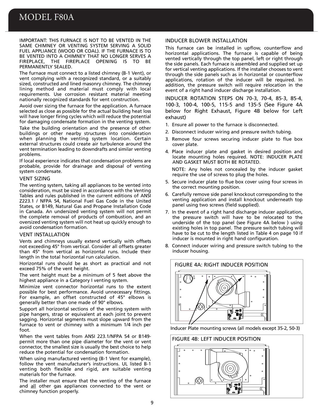
INDUCER ROTATION STEPS ON 70-3, 70-4, 85-3, 85-4, 100-3, 100-4, 100-5, 115-5 and 135-5 (See Figure 4A below for Right Exhaust, Figure 4B below for Left exhaust)
1.Ensure all power to the furnace is disconnected.
2.Disconnect inducer wiring and pressure switch tubing.
3.Remove four screws securing inducer plate to flue box cover plate.
4.Place inducer plate and gasket in desired position and locate mounting holes required. NOTE: INDUCER PLATE AND GASKET MUST BOTH BE ROTATED.
NOTE: Any holes not concealed by the inducer gasket require the use of screws to plug the holes.
5.Secure inducer plate to flue box cover using four screws in the correct mounting position.
6.Carefully remove side panel knockout corresponding to the venting application and install knockout underneath top panel using two screws (field supplied).
7.In the event of a right hand discharge inducer application, the pressure switch will have to be relocated to the underside of the top panel (see Figure 4A below ) using existing holes in top panel. The pressure switch tubing will have to be cut to the length listed in Table 4 on page 10 if inducer is mounted in right hand configuration.
8.Connect inducer wiring and pressure switch tubing to the inducer housing.
FIGURE 4A: RIGHT INDUCER POSITION
Inducer Plate mounting screws (all models except 35-2, 50-3)
FIGURE 4B: LEFT INDUCER POSITION