CHECKING FURNACE INPUT
•The natural gas supply pressure should be a maximum of 7 inches w.c. and minimum of 5 inches w.c.
•The burner manifold pressure is normally set to 3.5 inches w.c. for natural gas
•The input rating of the furnace is based on 1075 / BTU/cu. ft. gas with a specific gravity of 0.60
Since heating values for the gas vary geographically, the actual furnace input and output will vary accordingly.
For example, natural gas with a 1000 BTU / cu. ft. heating value will reduce the input to 93% of the rated input. Natural gas with a 1100 BTU / cu. ft. heating value will increase the input to approximately 103% of the rated input. This is not usually a problem; however, adjustments to compensate for this can be made by minor adjustments to the burner manifold pressure or by changing the burner orifice size.
In the previous example where the heating value of the gas is 1100 BTU / cu. ft., the burner manifold pressure can be reduced .3% to 3.4% w.c. which is within the ±0.30 inches w.c. specification to bring the input into compliance. Refer also to Setting the Gas Pressure, and contact the fuel supplier for specific gas heating content values.
If using a gas meter to check the furnace input, be sure that all gas fired appliances other than the furnace are off during the test.
Any adjustments to the burner manifold pressure should be carried out with the use of a manometer or calibrated magnehelic gauge. Do not adjust the gas valve pressure regulator more than ± 0.30 inches water column.
The formula for determining the furnace input via the gas meter test dial is:
Input =Heating Value of Gas X 3600
Time in Sec. for 1 cu. ft
Where:
Input is expressed in BTU / Hr.
Heating value of the gas is expressed in BTU / cubic feet
Time means time required for the test dial to indicate 1 cubic foot in seconds.
If using a gas meter with SI (metric) units:
1 cubic foot = 0.0283 cubic meters.
1 cubic meter = 35.315 cubic foot.
0.01cubic meter = 0.3531 cubic foot.
0.5 cubic meter = 1.766 cubic feet.
IMPORTANT: NEVER ADJUST THE INPUT OF THE FURNACE TO EXCEED THE INPUT SHOWN ON THE RATING PLATE.
WARM AIR FURNACE
TEMPERATURE RISE CHECK
When the duct system is complete and the air filter or filters are in place, determine if the airflow is correct.
1.Insert a duct thermometer in the supply air duct. The thermometer should be placed as close as practical to the furnace, but out of the "line of sight" of the heat exchanger (this prevents false readings owing to radiant heat). Ensure that the thermometer location is within the duct air stream. Avoid locations such as the inside radius of an elbow, etc.
2.Insert a duct thermometer in the return air duct as close to the furnace as practical. Ensure that the thermometer location will be unaffected by humidifier bypass ducts, etc. Choose a location well within the main air stream.
3.Operate the furnace long enough to obtain steady state conditions.
4.When the two thermometers have stabilized, usually within 5 - 8 minutes, compare the two readings. Subtract the return air temperature from the supply air
temperature. The difference is the temperature rise, also called ΔT.
5.Compare the measured ΔT to the temperature rise range shown on the rating plate.
Unless stated differently on the rating plate, the temperature rise should normally range between 30° to 60°F or 35° to 65°F. When adjusting the temperature rise, the ideal temperature is approximately mid-range.
If the measured ΔT is above the approved temperature range, there is too little airflow. The airflow must be increased by selecting a faster fan speed, removing restrictions in the ductwork, or adding supply or return ductwork.
If the measured ΔT is too low, there is too much airflow. Use a lower speed tap on the multispeed motor. The blow- er speed is changed at the integrated furnace control. Remove the wire from the “HEAT-H” terminal of the
50A55-20 integrated furnace control and plug in the desired wire on the “HEAT-H” terminal. When this config- uration is used, the following color codes are used: Black - High Speed, Blue - Medium-High Speed, Yellow - Medium- Low Speed and Red - Low Speed. The unused leads are connected to the M1, M2 terminals on the 50A55-20 inte- grated furnace control.
IMPORTANT: If the heating speed and cooling speed are to be the same, remove the cooling lead from the control, tape it off, then install a "piggyback" connector from the control "HEAT" terminal to the "COOL" terminal. UNDER NO CIRCUMSTANCE MAY TWO MOTOR WINDINGS BE POWERED SIMULTANEOUSLY.
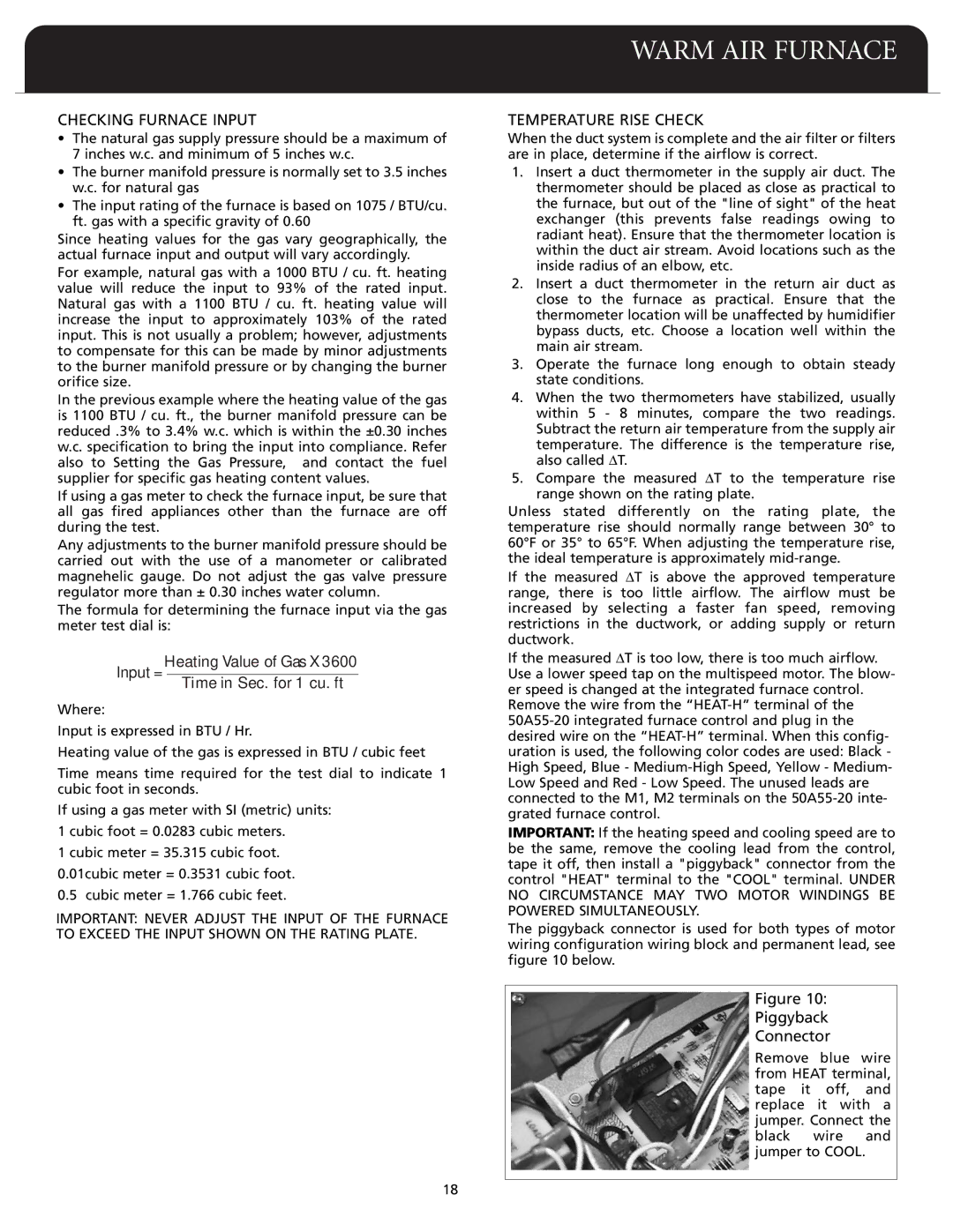
The piggyback connector is used for both types of motor wiring configuration wiring block and permanent lead, see figure 10 below.
Figure 10:
Piggyback
Connector
Remove blue wire from HEAT terminal, tape it off, and replace it with a jumper. Connect the black wire and jumper to COOL.