•If the furnace is to be located in an area where the combustion air is laden with chemical compounds such as bromine, chlorine or fluorine, as may be found in swimming pool chemicals, laundry detergents, etc., use outdoor air for combustion. These compounds when exposed to flame, form acids, which attack the heat exchanger and other components.
A partial list of these contaminants includes:
-Aerosols, particularly CFC based aerosols
-Air fresheners
-“Airplane” glue and similar cements
-Ammonia, as is commonly found in permanent wave solutions used in women’s hair dressing salons
-Anti-static fabric softeners used in clothes dryers
-Carbon tetrachloride
-Chlorinated cleaners and waxes
-Chlorine and bromine based swimming pool chemicals and treatments
-Deicing salts or chemicals, rock salt, etc.
-Dry cleaning solutions such as perchloroethylene
-Halogen based refrigerants including R-12 and R-22
-Hydrochloric acid, muriatic acid, or other acid based masonry washing compounds
-Polyurethane and similar derivatives fumes
-Printer’s inks, paint removers, furniture strippers, varnishes, varsol, toluene, etc.
-Water softener salts and chemicals
INSTALLATION POSITIONS
NONSUSPENDED INSTALLATION
Maintain clearances to combustibles as outlined in Table 2 on page 5. The furnace must be supported in such a way as to not allow twisting or sagging of the cabinet.
SUSPENDED INSTALLATION
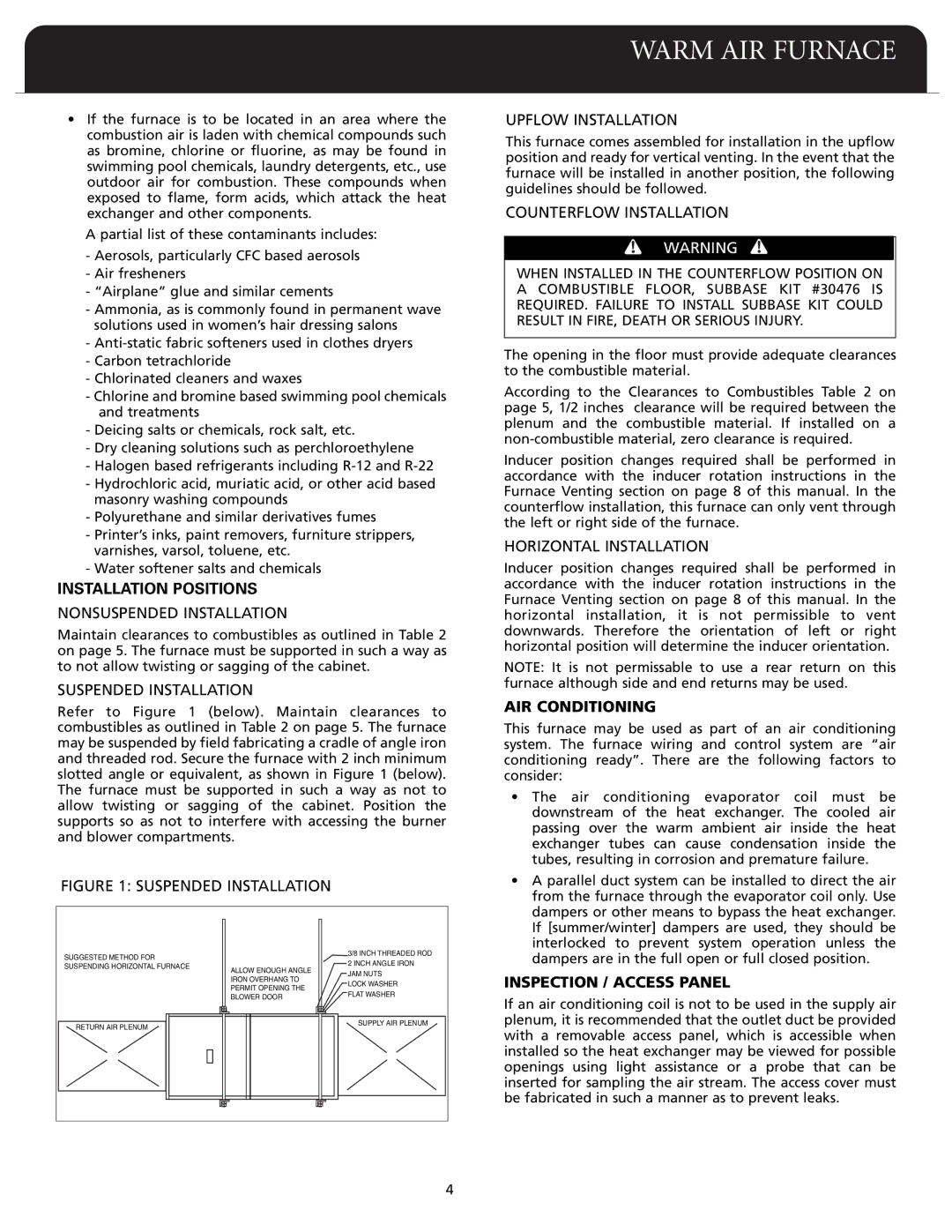
Refer to Figure 1 (below). Maintain clearances to combustibles as outlined in Table 2 on page 5. The furnace may be suspended by field fabricating a cradle of angle iron and threaded rod. Secure the furnace with 2 inch minimum slotted angle or equivalent, as shown in Figure 1 (below). The furnace must be supported in such a way as not to allow twisting or sagging of the cabinet. Position the supports so as not to interfere with accessing the burner and blower compartments.
FIGURE 1: SUSPENDED INSTALLATION
| SUGGESTED METHOD FOR | | | /83I | NCH THREADED | ROD |
| | | 2 INCH ANGLE IRON |
| SUSPENDING HORIZONTAL FURNACE | ALLOW ENOUGH ANGLE |
| JAM NUTS | |
| | | |
| | | IRONANGOVERHTO | |
| | | OCKL WA | SHER | |
| | IT O ERMP | PENING THE | |
| | LATF WA | SHER | |
| | ER | LOWB | DOOR | |
| | | | | |
| ETURN AI | R PLENUM | | | | UPPLYS AIR PL | ENUM |
| | | | | | |
| | | | | | | | 4 |
WARM AIR FURNACE
UPFLOW INSTALLATION
This furnace comes assembled for installation in the upflow position and ready for vertical venting. In the event that the furnace will be installed in another position, the following guidelines should be followed.
COUNTERFLOW INSTALLATION
WARNING
WHEN INSTALLED IN THE COUNTERFLOW POSITION ON A COMBUSTIBLE FLOOR, SUBBASE KIT #30476 IS REQUIRED. FAILURE TO INSTALL SUBBASE KIT COULD RESULT IN FIRE, DEATH OR SERIOUS INJURY.
The opening in the floor must provide adequate clearances to the combustible material.
According to the Clearances to Combustibles Table 2 on page 5, 1/2 inches clearance will be required between the plenum and the combustible material. If installed on a non-combustible material, zero clearance is required.
Inducer position changes required shall be performed in accordance with the inducer rotation instructions in the Furnace Venting section on page 8 of this manual. In the counterflow installation, this furnace can only vent through the left or right side of the furnace.
HORIZONTAL INSTALLATION
Inducer position changes required shall be performed in accordance with the inducer rotation instructions in the Furnace Venting section on page 8 of this manual. In the horizontal installation, it is not permissible to vent downwards. Therefore the orientation of left or right horizontal position will determine the inducer orientation.
NOTE: It is not permissable to use a rear return on this furnace although side and end returns may be used.
AIR CONDITIONING
This furnace may be used as part of an air conditioning system. The furnace wiring and control system are “air conditioning ready”. There are the following factors to consider:
•The air conditioning evaporator coil must be downstream of the heat exchanger. The cooled air passing over the warm ambient air inside the heat exchanger tubes can cause condensation inside the tubes, resulting in corrosion and premature failure.
•A parallel duct system can be installed to direct the air from the furnace through the evaporator coil only. Use dampers or other means to bypass the heat exchanger. If [summer/winter] dampers are used, they should be interlocked to prevent system operation unless the dampers are in the full open or full closed position.
INSPECTION / ACCESS PANEL
If an air conditioning coil is not to be used in the supply air plenum, it is recommended that the outlet duct be provided with a removable access panel, which is accessible when installed so the heat exchanger may be viewed for possible openings using light assistance or a probe that can be inserted for sampling the air stream. The access cover must be fabricated in such a manner as to prevent leaks.