CONTROLS AND SWITCHES
All models are provided with four pressure switches. These switches are essential to the safe and proper operation of the unit. All switches are wired in series. The controller is set up to shut the unit down whenever there is a failure of any of the switches. It is important to understand the purpose of each switch.
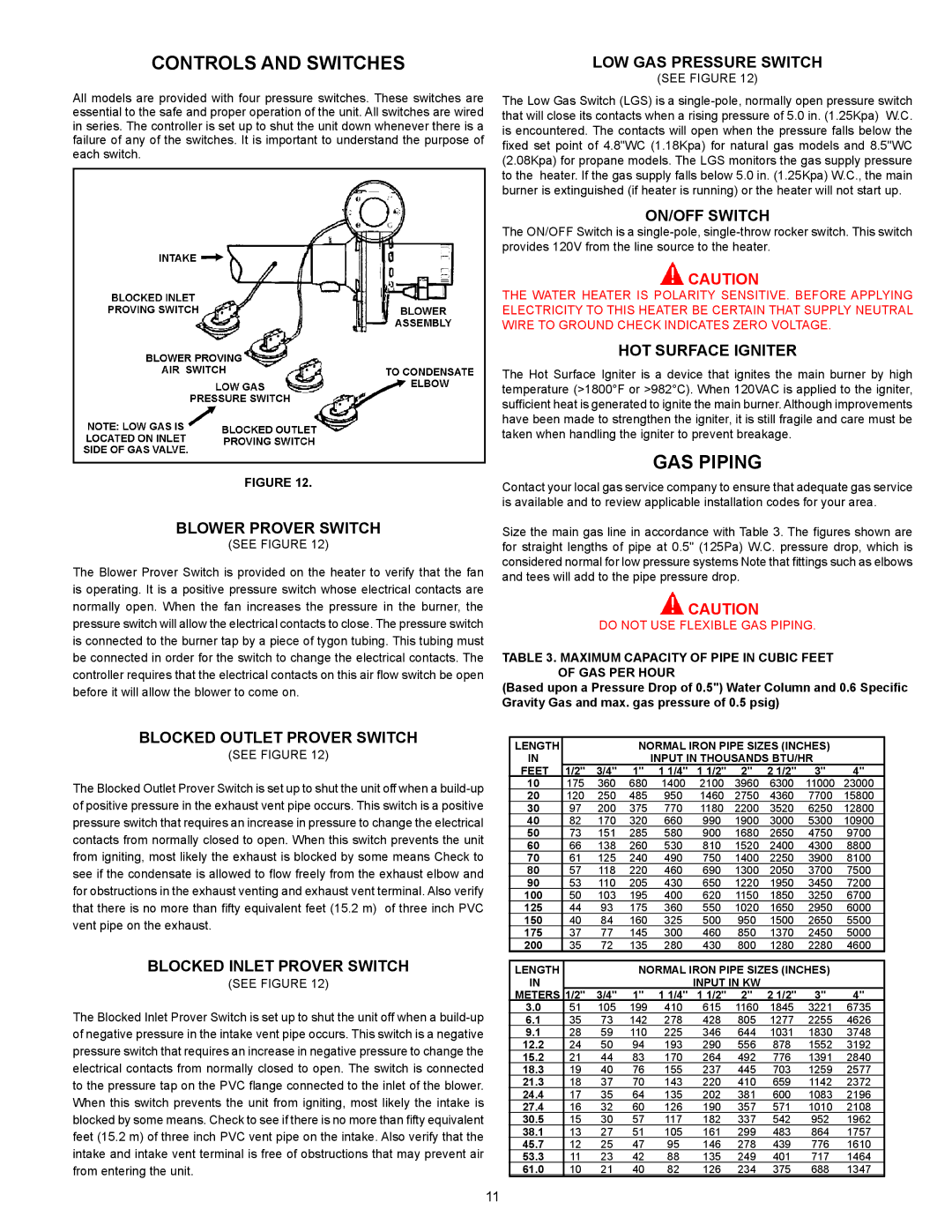
FIGURE 12.
BLOWER PROVER SWITCH
(SEE FIGURE 12)
The Blower Prover Switch is provided on the heater to verify that the fan is operating. It is a positive pressure switch whose electrical contacts are normally open. When the fan increases the pressure in the burner, the pressure switch will allow the electrical contacts to close. The pressure switch is connected to the burner tap by a piece of tygon tubing. This tubing must be connected in order for the switch to change the electrical contacts. The
controller requires that the electrical contacts on this air flow switch be open
before it will allow the blower to come on.
BLOCKED OUTLET PROVER SWITCH
(SEE FIGURE 12)
The Blocked Outlet Prover Switch is set up to shut the unit off when a
contacts from normally closed to open. When this switch prevents the unit from igniting, most likely the exhaust is blocked by some means Check to
see if the condensate is allowed to flow freely from the exhaust elbow and
for obstructions in the exhaust venting and exhaust vent terminal. Also verify
that there is no more than fifty equivalent feet (15.2 m) of three inch PVC
vent pipe on the exhaust.
BLOCKED INLET PROVER SWITCH
(SEE FIGURE 12)
The Blocked Inlet Prover Switch is set up to shut the unit off when a
of negative pressure in the intake vent pipe occurs. This switch is a negative pressure switch that requires an increase in negative pressure to change the electrical contacts from normally closed to open. The switch is connected
to the pressure tap on the PVC flange connected to the inlet of the blower.
When this switch prevents the unit from igniting, most likely the intake is
blocked by some means. Check to see if there is no more than fifty equivalent
feet (15.2 m) of three inch PVC vent pipe on the intake. Also verify that the intake and intake vent terminal is free of obstructions that may prevent air from entering the unit.
LOW GAS PRESSURE SWITCH
(SEE FIGURE 12)
The Low Gas Switch (LGS) is a
ON/OFF SWITCH
The ON/OFF Switch is a
![]() CAUTION
CAUTION
THE WATER HEATER IS POLARITY SENSITIVE. BEFORE APPLYING ELECTRICITY TO THIS HEATER BE CERTAIN THAT SUPPLY NEUTRAL WIRE TO GROUND CHECK INDICATES ZERO VOLTAGE.
HOT SURFACE IGNITER
The Hot Surface Igniter is a device that ignites the main burner by high temperature (>1800°F or >982°C). When 120VAC is applied to the igniter, sufficient heat is generated to ignite the main burner. Although improvements have been made to strengthen the igniter, it is still fragile and care must be taken when handling the igniter to prevent breakage.
GAS PIPING
Contact your local gas service company to ensure that adequate gas service is available and to review applicable installation codes for your area.
Size the main gas line in accordance with Table 3. The figures shown are for straight lengths of pipe at 0.5" (125Pa) W.C. pressure drop, which is considered normal for low pressure systems Note that fittings such as elbows and tees will add to the pipe pressure drop.
![]() CAUTION
CAUTION
DO NOT USE FLEXIBLE GAS PIPING.
TABLE 3. MAXIMUM CAPACITY OF PIPE IN CUBIC FEET OF GAS PER HOUR
(Based upon a Pressure Drop of 0.5") Water Column and 0.6 Specific Gravity Gas and max. gas pressure of 0.5 psig)
LENGTH |
|
| NORMAL IRON PIPE SIZES (INCHES) |
| |||||
IN |
|
|
| INPUT IN THOUSANDS BTU/HR |
| ||||
FEET | 1/2" | 3/4" | 1" | 1 1/4" | 1 1/2" | 2" | 2 1/2" | 3" | 4" |
10 | 175 | 360 | 680 | 1400 | 2100 | 3960 | 6300 | 11000 | 23000 |
20 | 120 | 250 | 485 | 950 | 1460 | 2750 | 4360 | 7700 | 15800 |
30 | 97 | 200 | 375 | 770 | 1180 | 2200 | 3520 | 6250 | 12800 |
40 | 82 | 170 | 320 | 660 | 990 | 1900 | 3000 | 5300 | 10900 |
50 | 73 | 151 | 285 | 580 | 900 | 1680 | 2650 | 4750 | 9700 |
60 | 66 | 138 | 260 | 530 | 810 | 1520 | 2400 | 4300 | 8800 |
70 | 61 | 125 | 240 | 490 | 750 | 1400 | 2250 | 3900 | 8100 |
80 | 57 | 118 | 220 | 460 | 690 | 1300 | 2050 | 3700 | 7500 |
90 | 53 | 110 | 205 | 430 | 650 | 1220 | 1950 | 3450 | 7200 |
100 | 50 | 103 | 195 | 400 | 620 | 1150 | 1850 | 3250 | 6700 |
125 | 44 | 93 | 175 | 360 | 550 | 1020 | 1650 | 2950 | 6000 |
150 | 40 | 84 | 160 | 325 | 500 | 950 | 1500 | 2650 | 5500 |
175 | 37 | 77 | 145 | 300 | 460 | 850 | 1370 | 2450 | 5000 |
200 | 35 | 72 | 135 | 280 | 430 | 800 | 1280 | 2280 | 4600 |
LENGTH |
|
| NORMAL IRON PIPE SIZES (INCHES) |
| |||||
IN |
|
|
|
| INPUT IN KW |
|
|
| |
METERS | 1/2" | 3/4" | 1" | 1 1/4" | 1 1/2" | 2" | 2 1/2" | 3" | 4" |
3.0 | 51 | 105 | 199 | 410 | 615 | 1160 | 1845 | 3221 | 6735 |
6.1 | 35 | 73 | 142 | 278 | 428 | 805 | 1277 | 2255 | 4626 |
9.1 | 28 | 59 | 110 | 225 | 346 | 644 | 1031 | 1830 | 3748 |
12.2 | 24 | 50 | 94 | 193 | 290 | 556 | 878 | 1552 | 3192 |
15.2 | 21 | 44 | 83 | 170 | 264 | 492 | 776 | 1391 | 2840 |
18.3 | 19 | 40 | 76 | 155 | 237 | 445 | 703 | 1259 | 2577 |
21.3 | 18 | 37 | 70 | 143 | 220 | 410 | 659 | 1142 | 2372 |
24.4 | 17 | 35 | 64 | 135 | 202 | 381 | 600 | 1083 | 2196 |
27.4 | 16 | 32 | 60 | 126 | 190 | 357 | 571 | 1010 | 2108 |
30.5 | 15 | 30 | 57 | 117 | 182 | 337 | 542 | 952 | 1962 |
38.1 | 13 | 27 | 51 | 105 | 161 | 299 | 483 | 864 | 1757 |
45.7 | 12 | 25 | 47 | 95 | 146 | 278 | 439 | 776 | 1610 |
53.3 | 11 | 23 | 42 | 88 | 135 | 249 | 401 | 717 | 1464 |
61.0 | 10 | 21 | 40 | 82 | 126 | 234 | 375 | 688 | 1347 |
11