Installation Instructions

1846197

7.Block the front wheels and jack up the rear of the machine and set on jack stands or wooden blocks. Remove the left drive tire. This will allow for easier access to the left hand pump.

8.Remove the left return hose and loosen the jam nut on the fitting on the pump. Rotate the fitting towards the rear of the machine and point it slightly upwards (see Figure 2). Tighten the jam nut.

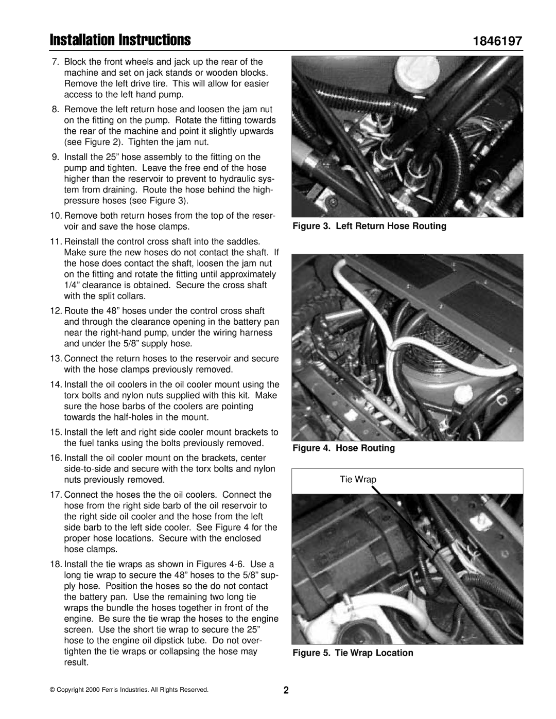
9.Install the 25” hose assembly to the fitting on the pump and tighten. Leave the free end of the hose higher than the reservoir to prevent to hydraulic sys- tem from draining. Route the hose behind the high- pressure hoses (see Figure 3).

10.Remove both return hoses from the top of the reser- voir and save the hose clamps.

11.Reinstall the control cross shaft into the saddles. Make sure the new hoses do not contact the shaft. If the hose does contact the shaft, loosen the jam nut on the fitting and rotate the fitting until approximately 1/4” clearance is obtained. Secure the cross shaft with the split collars.

12.Route the 48” hoses under the control cross shaft and through the clearance opening in the battery pan near the right-hand pump, under the wiring harness and under the 5/8” supply hose.

13.Connect the return hoses to the reservoir and secure with the hose clamps previously removed.

14.Install the oil coolers in the oil cooler mount using the torx bolts and nylon nuts supplied with this kit. Make sure the hose barbs of the coolers are pointing towards the half-holes in the mount.

15.Install the left and right side cooler mount brackets to the fuel tanks using the bolts previously removed.

16.Install the oil cooler mount on the brackets, center side-to-side and secure with the torx bolts and nylon nuts previously removed.

17.Connect the hoses the the oil coolers. Connect the hose from the right side barb of the oil reservoir to the right side oil cooler and the hose from the left side barb to the left side cooler. See Figure 4 for the proper hose locations. Secure with the enclosed hose clamps.

18.Install the tie wraps as shown in Figures 4-6. Use a long tie wrap to secure the 48” hoses to the 5/8” sup- ply hose. Position the hoses so the do not contact the battery pan. Use the remaining two long tie wraps the bundle the hoses together in front of the engine. Be sure the tie wrap the hoses to the engine screen. Use the short tie wrap to secure the 25” hose to the engine oil dipstick tube. Do not over- tighten the tie wraps or collapsing the hose may result.

Figure 3. Left Return Hose Routing

Figure 4. Hose Routing

Tie Wrap

Figure 5. Tie Wrap Location

© Copyright 2000 Ferris Industries. All Rights Reserved.

2

Page 2
Image 2
Ferris Industries ZT2354 installation instructions Installation Instructions, 1846197

1846197, ZT2354 specifications

Ferris Industries has established itself as a leader in the outdoor power equipment sector, and one of its standout offerings is the ZT2354,1846197 zero-turn mower. Designed with both professional landscapers and avid homeowners in mind, this mower combines performance, efficiency, and durability, making it an exceptional choice for any lawn care task.

One of the most notable features of the ZT2354 is its innovative zero-turn design. This allows for an unparalleled maneuverability, enabling users to navigate around obstacles and tight spaces with ease. The mower's dual-lever control system provides intuitive handling, giving operators the ability to make precise turns and curves, resulting in a beautifully manicured lawn.

Equipped with a powerful engine, the ZT2354 delivers impressive cutting performance. The mower typically features a high-performance engine that provides ample horsepower, ensuring that even dense grass is cut cleanly and efficiently. Additionally, the mower’s deck size, usually around 54 inches, facilitates quick mowing of large areas, reducing the time spent on lawn care.

The ZT2354 is also designed with operator comfort in mind. It often includes a plush seat with armrests and ergonomic controls, reducing fatigue during long mowing sessions. The intuitive dashboard provides key information such as fuel level and speed, allowing the user to stay informed throughout the mowing process.

Durability is a cornerstone of Ferris Industries' design philosophy, and the ZT2354 is no exception. Constructed with robust materials, including reinforced frames and heavy-duty steel decks, this mower is built to withstand the rigors of regular use. Moreover, features such as anti-scalp wheels ensure that the mower maintains a consistent cutting height, preventing damage to the lawn.

In terms of technology, the ZT2354 is often equipped with advanced features like an adjustable cutting height system, offering multiple options for grass length, and a high-efficiency cooling system that keeps the engine running smoothly in various conditions. These enhancements contribute to a superior mowing experience, optimizing both performance and longevity.

In summary, the Ferris Industries ZT2354,1846197 zero-turn mower combines cutting-edge technology with user-friendly design, making it a top choice for those looking to achieve professional-grade results in lawn care. Whether you are maintaining a residential yard or managing a larger landscape, this mower is engineered to deliver efficiency, comfort, and exceptional performance.