Gas Supply
GAS SUPPLY CONNECTION
The product is supplied set up for Natural Gas. This cooktop is suitable for installation with Natural Gas, or LP Gas. Refer to table for the relevant pressures and appropriate injector sizes.
-Gas connection to the product must use the elbow supplied. The regulator will not seal if installed without it.
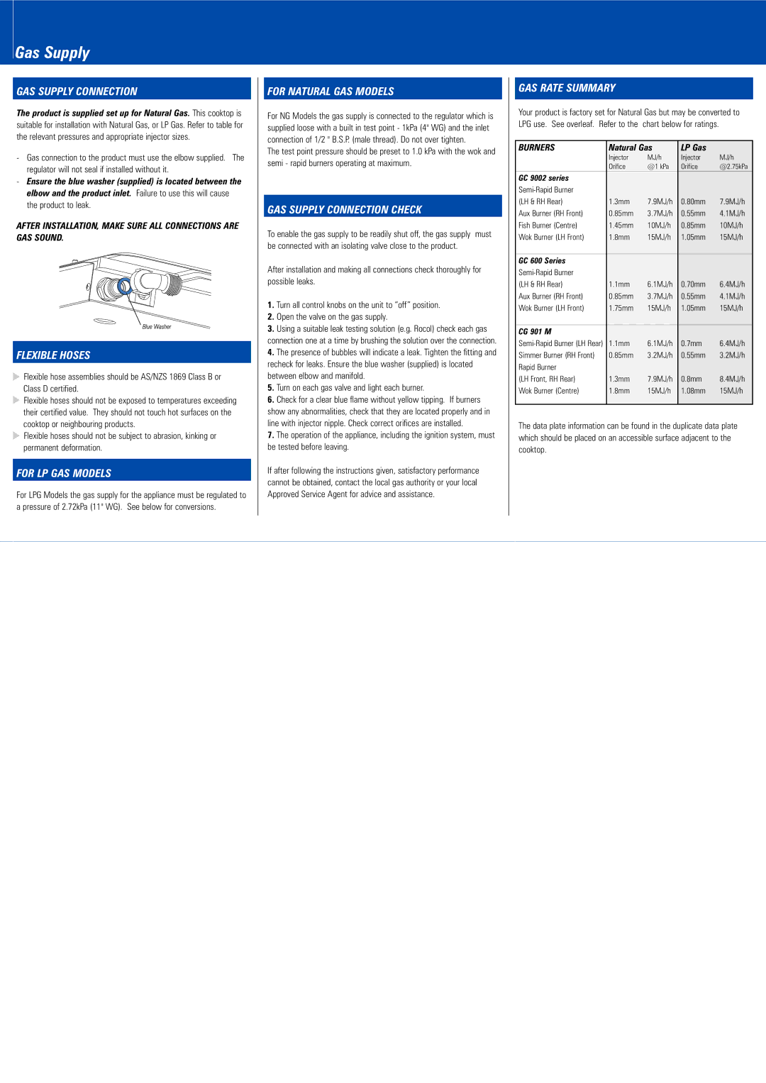
-Ensure the blue washer (supplied) is located between the elbow and the product inlet. Failure to use this will cause the product to leak.
AFTER INSTALLATION, MAKE SURE ALL CONNECTIONS ARE GAS SOUND.
FLEXIBLE HOSES
![]() Flexible hose assemblies should be AS/NZS 1869 Class B or Class D certified.
Flexible hose assemblies should be AS/NZS 1869 Class B or Class D certified.
![]() Flexible hoses should not be exposed to temperatures exceeding their certified value. They should not touch hot surfaces on the cooktop or neighbouring products.
Flexible hoses should not be exposed to temperatures exceeding their certified value. They should not touch hot surfaces on the cooktop or neighbouring products.
![]() Flexible hoses should not be subject to abrasion, kinking or permanent deformation.
Flexible hoses should not be subject to abrasion, kinking or permanent deformation.
FOR LP GAS MODELS
For LPG Models the gas supply for the appliance must be regulated to a pressure of 2.72kPa (11" WG). See below for conversions.
FOR NATURAL GAS MODELS
For NG Models the gas supply is connected to the regulator which is supplied loose with a built in test point - 1kPa (4" WG) and the inlet connection of 1/2 " B.S.P. (male thread). Do not over tighten.
The test point pressure should be preset to 1.0 kPa with the wok and semi - rapid burners operating at maximum.
GAS SUPPLY CONNECTION CHECK
To enable the gas supply to be readily shut off, the gas supply must be connected with an isolating valve close to the product.
After installation and making all connections check thoroughly for possible leaks.
1.Turn all control knobs on the unit to “off” position.
2.Open the valve on the gas supply.
3.Using a suitable leak testing solution (e.g. Rocol) check each gas connection one at a time by brushing the solution over the connection.
4.The presence of bubbles will indicate a leak. Tighten the fitting and recheck for leaks. Ensure the blue washer (supplied) is located between elbow and manifold.
5.Turn on each gas valve and light each burner.
6.Check for a clear blue flame without yellow tipping. If burners
show any abnormalities, check that they are located properly and in line with injector nipple. Check correct orifices are installed.
7.The operation of the appliance, including the ignition system, must be tested before leaving.
If after following the instructions given, satisfactory performance cannot be obtained, contact the local gas authority or your local Approved Service Agent for advice and assistance.
GAS RATE SUMMARY
Your product is factory set for Natural Gas but may be converted to LPG use. See overleaf. Refer to the chart below for ratings.
BURNERS | Natural Gas | LP Gas |
| |
| Injector | MJ/h | Injector | MJ/h |
| Orifice | @1 kPa | Orifice | @2.75kPa |
GC 9002 series |
|
|
|
|
|
|
|
| |
(LH & RH Rear) | 1.3mm | 7.9MJ/h | 0.80mm | 7.9MJ/h |
Aux Burner (RH Front) | 0.85mm | 3.7MJ/h | 0.55mm | 4.1MJ/h |
Fish Burner (Centre) | 1.45mm | 10MJ/h | 0.85mm | 10MJ/h |
Wok Burner (LH Front) | 1.8mm | 15MJ/h | 1.05mm | 15MJ/h |
|
|
|
|
|
GC 600 Series |
|
|
|
|
|
|
|
| |
(LH & RH Rear) | 1.1mm | 6.1MJ/h | 0.70mm | 6.4MJ/h |
Aux Burner (RH Front) | 0.85mm | 3.7MJ/h | 0.55mm | 4.1MJ/h |
Wok Burner (LH Front) | 1.75mm | 15MJ/h | 1.05mm | 15MJ/h |
|
|
|
|
|
CG 901 M |
|
|
|
|
1.1mm | 6.1MJ/h | 0.7mm | 6.4MJ/h | |
Simmer Burner (RH Front) | 0.85mm | 3.2MJ/h | 0.55mm | 3.2MJ/h |
Rapid Burner |
|
|
|
|
(LH Front, RH Rear) | 1.3mm | 7.9MJ/h | 0.8mm | 8.4MJ/h |
Wok Burner (Centre) | 1.8mm | 15MJ/h | 1.08mm | 15MJ/h |
|
|
|
|
|
The data plate information can be found in the duplicate data plate which should be placed on an accessible surface adjacent to the cooktop.