6
Installation instructions
Before you install the oven, make sure that
the benchtop and oven cavity are square and level, and are the required dimensions
the installation will comply with all clearance requirements and applicable standards and regulations
a suitable isolating switch providing full disconnection from the mains power supply is incorporated in the permanent wiring, mounted and positioned to comply with the local wiring rules and regulations. The isolating switch must be of an approved type and provide a 3 mm air gap contact separation in all poles (or in all active [phase] conductors if the local wiring rules allow for this variation of the requirements)
the isolating switch will be easily accessible to the customer with the oven installed
there is at least 1.5 m (and not more than 2 m) free length of power supply cable within the cavity for ease of installation and servicing
the oven connection socket (if fitted) is outside the cavity if the oven is flush to the rear wall the oven will rest on a surface that can support its weight
the height from the floor suits the customer
you consult local building authorities and
When you have installed the oven, make sure that the oven door can open fully without obstruction
the power supply cable does not touch any hot metal parts the isolating switch is easily accessible by the customer
you complete the ‘Final checklist’ at the end of these installation instructions.
Unpacking the oven
Remove all packaging and dispose of it responsibly. Recycle items that you can.
When you remove the oven from the carton, place it onto wooden blocks or similar supports to prevent damaging the lower trim.
Important!
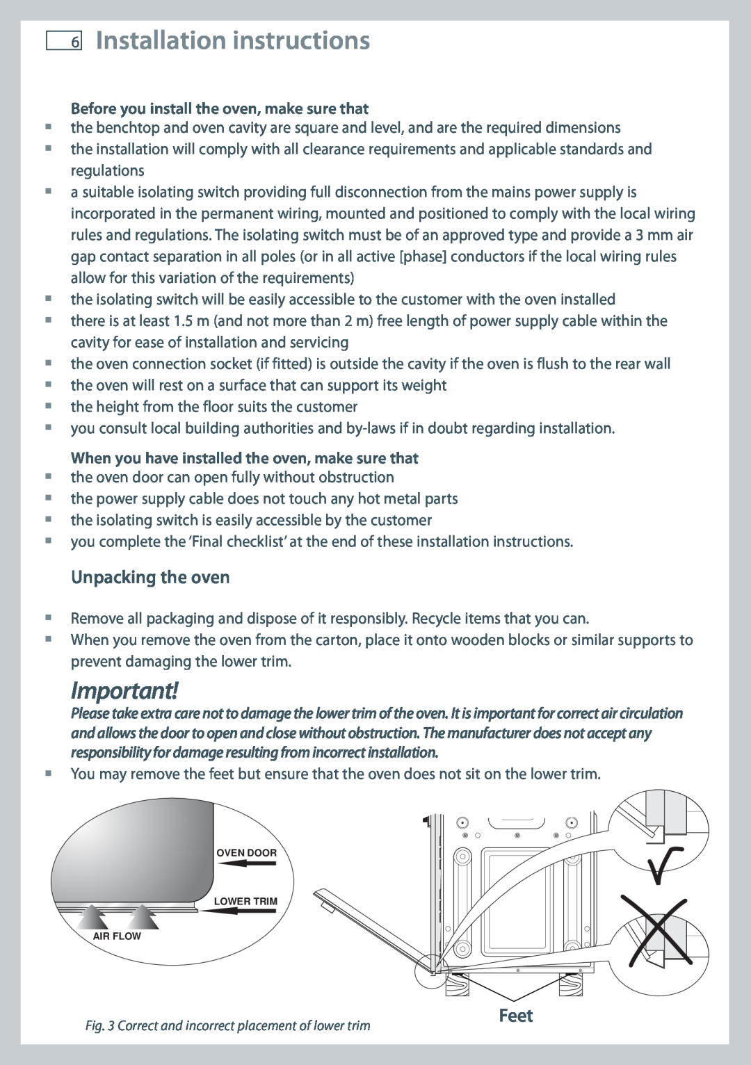
Please take extra care not to damage the lower trim of the oven. It is important for correct air circulation and allows the door to open and close without obstruction. The manufacturer does not accept any responsibility for damage resulting from incorrect installation.
You may remove the feet but ensure that the oven does not sit on the lower trim.
![]() LOWER TRIM
LOWER TRIM
OVEN DOOR
LOWER TRIM
AIR FLOW
Fig. 3 Correct and incorrect placement of lower trim