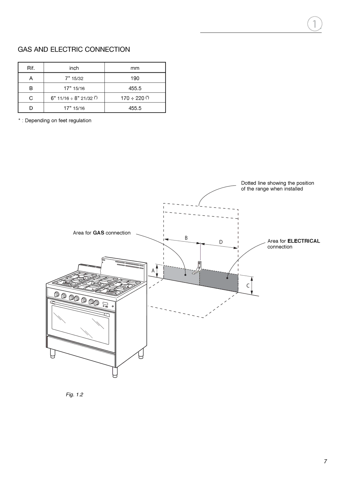
GAS AND ELECTRIC CONNECTION
Rif. | inch | mm |
|
|
|
A | 7” 15/32 | 190 |
|
|
|
B | 17” 15/16 | 455.5 |
|
|
|
C | 6” 11/16 ÷ 8” 21/32 (*) | 170 ÷ 220 (*) |
D | 17” 15/16 | 455.5 |
|
|
|
* : Depending on feet regulation
Area for GAS connection
B
A
Fig. 1.2
1a
Dotted line showing the position of the range when installed
DArea for ELECTRICAL connection
C
7
