Model D2424LV Quick Operation Guide
Basic digital recording
In the following, basic
Selecting Digital In
<About Digital In selection>
For setup items of digital in, in addition to the initial setting of "Analog," "SPDIF: Async," "SPDIF: Sync," "adat: Async" or "adat: Sync" can be selected and setup to match the application.
"Analog" indicates that none of the tracks are assigned to digital in and is the setting in which digital signals cannot be input to any of the [DATA INPUT] connectors.
"SPDIF:Async" and "SPDIF: Sync" are used when assign- ing S/P DIF signals (L, R) from external digital equip- ment to tracks 1 and 2 of D2424LV, and selected to digital in asynchronous (Async) or synchronous (Sync) depending on the system in
use. In this case, [DATA INPUT]
"adat:Async" and "adat: Sync" are used to assign adat signals (ch
In this case, all [DATA INPUT] connctors can be used and each input port will function as shown below.
[DATA INPUT]
[DATA INPUT]
[DATA INPUT]
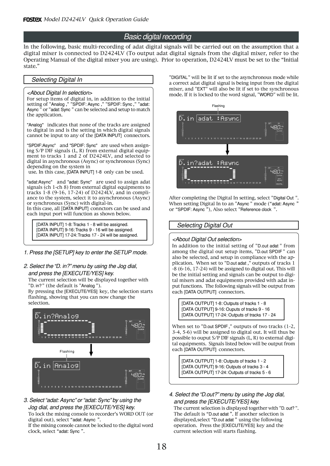
1.Press the [SETUP] key to enter the SETUP mode.
2.Select the “D. in?” menu by using the Jog dial,
and press the [EXECUTE/YES] key.
The current selection will be displayed together with "D. in?" (the default is "Analog").
By pressing the [EXECUTE/YES] key, the selection starts flashing, showing that you can now change the selection.
SETUP
OL |
|
|
|
|
|
|
|
|
|
|
|
|
|
|
|
|
|
|
|
|
|
|
|
|
|
|
|
|
|
|
|
|
|
|
| OL | BIT | 24 |
|
|
|
|
|
|
|
|
|
|
|
|
|
|
| ||||||||||||||||||||||||
0 |
|
|
|
| 0 |
|
| |||||||||||||||||||||||||||||||
|
|
|
|
| ||||||||||||||||||||||||||||||||||
3 |
|
|
|
|
| 3 |
| FS | ||||||||||||||||||||||||||||||
|
|
|
|
| ||||||||||||||||||||||||||||||||||
6 |
|
|
|
|
|
| 6 |
| ||||||||||||||||||||||||||||||
|
|
|
|
|
| |||||||||||||||||||||||||||||||||
9 |
|
|
| 9 |
| kHz | ||||||||||||||||||||||||||||||||
|
|
| ||||||||||||||||||||||||||||||||||||
12 |
|
|
| 12 |
| CLOCK | ||||||||||||||||||||||||||||||||
|
|
| ||||||||||||||||||||||||||||||||||||
18 |
|
|
| 18 |
| |||||||||||||||||||||||||||||||||
|
|
| ||||||||||||||||||||||||||||||||||||
24 |
|
|
| 24 |
|
| ||||||||||||||||||||||||||||||||
|
|
|
| |||||||||||||||||||||||||||||||||||
30 |
|
|
| 30 |
|
| ||||||||||||||||||||||||||||||||
|
|
|
| |||||||||||||||||||||||||||||||||||
42 |
|
|
|
| 42 |
|
| |||||||||||||||||||||||||||||||
∞ |
|
|
|
|
|
|
|
|
|
|
|
|
|
|
|
|
|
|
|
|
|
|
|
|
|
|
|
|
|
|
|
|
|
|
| ∞ |
|
|
1 2 3 4 5 6 7 8 9 10 11 12 13 14 15 16 17 18 19 20 21 22 23 24
Flashing
SETUP
OL | OL | BIT | 24 |
0 | 0 |
|
|
3 | 3 |
| FS |
6 | 6 |
| |
9 | 9 |
| kHz |
12 | 12 |
| CLOCK |
18 | 18 |
| |
24 | 24 |
|
|
30 | 30 |
|
|
42 | 42 |
|
|
∞ | ∞ |
|
|
1 2 3 4 5 6 7 8 9 10 11 12 13 14 15 16 17 18 19 20 21 22 23 24
3. Select “adat: Async” or “adat: Sync” by using the Jog dial, and press the [EXECUTE/YES] key.
To lock the mixing console to recorder's WORD OUT (or digital out), select “adat: Async”.
If the mixing console cannot be locked to the digital word clock, select “adat: Sync”.
"DIGITAL" will be lit if set to the asynchronous mode while a correct adat digital signal is being input from the digital mixer, and "EXT" will also be lit if set to the synchronous mode. If it is locked to the word signal, "WORD" will be lit.
Flashing
SETUP
OL | OL | BIT | 24 |
0 | 0 |
|
|
3 | 3 |
| FS |
6 | 6 |
| |
9 | 9 |
| kHz |
12 | 12 |
| CLOCK |
18 | 18 |
| |
24 | 24 |
|
|
30 | 30 |
|
|
42 | 42 |
|
|
∞ | ∞ |
|
|
1 2 3 4 5 6 7 8 9 10 11 12 13 14 15 16 17 18 19 20 21 22 23 24
SETUP
OL |
|
|
|
|
|
|
|
|
|
|
|
|
|
|
|
|
|
|
|
|
|
|
|
|
|
|
|
|
|
|
|
|
|
|
|
|
| OL | BIT | 24 | |
|
|
|
|
|
|
|
|
|
|
|
|
|
|
|
|
|
|
|
|
|
|
|
|
|
|
|
|
|
|
|
|
|
|
|
|
| |||||
0 |
|
|
|
|
|
|
|
|
|
|
|
|
|
|
|
|
|
|
|
|
|
|
|
|
|
|
|
|
|
|
|
|
|
|
|
|
|
| 0 |
|
|
|
|
|
|
|
|
|
|
|
|
|
|
|
|
|
|
|
|
|
|
|
|
|
|
|
|
|
|
|
|
|
|
|
|
|
|
|
|
|
| ||
3 |
|
|
|
|
|
|
|
|
|
|
|
|
|
|
|
|
|
|
|
|
|
|
|
|
|
|
|
|
|
|
|
|
|
|
|
|
|
| 3 |
| FS |
|
|
|
|
|
|
|
|
|
|
|
|
|
|
|
|
|
|
|
|
|
|
|
|
|
|
|
|
|
|
|
|
|
|
|
|
|
|
| |||
6 |
|
|
|
|
|
|
|
|
|
|
|
|
|
|
|
|
|
|
|
|
|
|
|
|
|
|
|
|
|
|
|
|
|
|
|
|
|
| 6 |
| |
|
|
|
|
|
|
|
|
|
|
|
|
|
|
|
|
|
|
|
|
|
|
|
|
|
|
|
|
|
|
|
|
|
|
|
|
|
|
| |||
9 |
|
|
|
|
|
|
|
|
|
|
|
|
|
|
|
|
|
|
|
|
|
|
|
|
|
|
|
|
|
|
|
|
|
|
|
|
|
| 9 |
| kHz |
|
|
|
|
|
|
|
|
|
|
|
|
|
|
|
|
|
|
|
|
|
|
|
|
|
|
|
|
|
|
|
|
|
|
|
|
|
|
| |||
12 |
|
|
|
|
|
|
|
|
|
|
|
|
|
|
|
|
|
|
|
|
|
|
|
|
|
|
|
|
|
|
|
|
|
|
|
|
|
| 12 |
| CLOCK |
|
|
|
|
|
|
|
|
|
|
|
|
|
|
|
|
|
|
|
|
|
|
|
|
|
|
|
|
|
|
|
|
|
|
|
|
|
|
| |||
18 |
|
|
|
|
|
|
|
|
|
|
|
|
|
|
|
|
|
|
|
|
|
|
|
|
|
|
|
|
|
|
|
|
|
|
|
|
|
| 18 |
| |
|
|
|
|
|
|
|
|
|
|
|
|
|
|
|
|
|
|
|
|
|
|
|
|
|
|
|
|
|
|
|
|
|
|
|
|
|
|
| |||
24 |
|
|
|
|
|
|
|
|
|
|
|
|
|
|
|
|
|
|
|
|
|
|
|
|
|
|
|
|
|
|
|
|
|
|
|
|
|
| 24 |
|
|
|
|
|
|
|
|
|
|
|
|
|
|
|
|
|
|
|
|
|
|
|
|
|
|
|
|
|
|
|
|
|
|
|
|
|
|
|
|
|
| ||
30 |
|
|
|
|
|
|
|
|
|
|
|
|
|
|
|
|
|
|
|
|
|
|
|
|
|
|
|
|
|
|
|
|
|
|
|
|
|
| 30 |
| EXT |
|
|
|
|
|
|
|
|
|
|
|
|
|
|
|
|
|
|
|
|
|
|
|
|
|
|
|
|
|
|
|
|
|
|
|
|
|
|
| |||
42 |
|
|
|
|
|
|
|
|
|
|
|
|
|
|
|
|
|
|
|
|
|
|
|
|
|
|
|
|
|
|
|
|
|
|
|
|
|
| 42 |
| |
∞ |
|
|
|
|
|
|
|
|
|
|
|
|
|
|
|
|
|
|
|
|
|
|
|
|
|
|
|
|
|
|
|
|
|
|
|
|
| ∞ |
| WORD | |
1 | 2 | 3 | 4 | 5 | 6 | 7 | 8 | 9 | 10 | 11 | 12 | 13 | 14 | 15 | 16 | 17 | 18 | 19 | 20 | 21 | 22 | 23 | 24 |
| DIGITAL | ||||||||||||||||
|
|
|
|
|
|
|
|
|
|
|
|
|
|
|
|
|
|
|
|
|
|
|
|
|
|
|
|
|
|
|
|
|
|
|
|
|
|
|
|
| |
After completing the Digital In setting, select "Digital Out". When setting Digital In to an "Async" mode (“adat: Async” or “SPDIF: Async”), Also select "Reference clock".
Selecting Digital Out
<About Digital Out selection>
In addition to the initial setting of "D.out adat" from among the digital out setup items, "D.out SPDIF" can also be selected, and setup in compliance with the ap- plication. When set to "D.out adat," outputs of tracks 1
[DATA OUTPUT]
[DATA OUTPUT]
[DATA OUTPUT]
When set to "D.out SPDIF," outputs of two tracks
[DATA OUTPUT]
[DATA OUTPUT]
[DATA OUTPUT]
4. Select the “D.out?” menu by using the Jog dial, and press the [EXECUTE/YES] key.
The current selection is displayed together with "D. out?". The default is “D.out adat”. If another selection is displayed,select “D.out adat” using the following operation. Press the [EXECUTE/YES] key and the current selection will starts flashing.
18