Freedom9 2420 user manual Identifying External Components, Front Panel, Rear Panel

Models: 2420

1 28
Download 28 pages 62.01 Kb
Page 9
Image 9

4 Identifying External Components

This chapter describes the front panel, rear panel, and LED indicators of the Switch.

4.1Front Panel

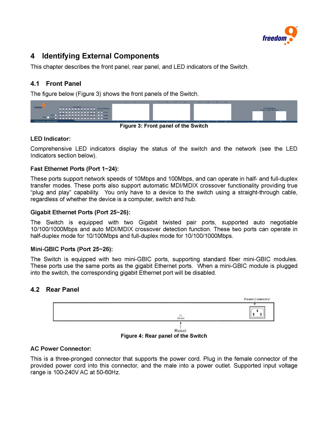
The figure below (Figure 3) shows the front panels of the Switch.

Figure 3: Front panel of the Switch

LED Indicator:

Comprehensive LED indicators display the status of the switch and the network (see the LED Indicators section below).

Fast Ethernet Ports (Port 1~24):

These ports support network speeds of 10Mbps and 100Mbps, and can operate in half- and full-duplex transfer modes. These ports also support automatic MDI/MDIX crossover functionality providing true “plug and play” capability. You only have to a device to the switch using a straight-through cable, regardless of whether the device is a computer, switch and hub.

Gigabit Ethernet Ports (Port 25~26):

The Switch is equipped with two Gigabit twisted pair ports, supported auto negotiable 10/100/1000Mbps and auto MDI/MDIX crossover detection function. These two ports can operate in half-duplex mode for 10/100Mbps and full-duplex mode for 10/100/1000Mbps.

Mini-GBIC Ports (Port 25~26):

The Switch is equipped with two mini-GBIC ports, supporting standard fiber mini-GBIC modules. These ports use the same ports as the gigabit Ethernet ports. When a mini-GBIC module is plugged into the switch, the corresponding gigabit Ethernet port will be disabled.

4.2Rear Panel

Figure 4: Rear panel of the Switch

AC Power Connector:

This is a three-pronged connector that supports the power cord. Plug in the female connector of the provided power cord into this connector, and the male into a power outlet. Supported input voltage range is 100-240V AC at 50-60Hz.

Page 9
Image 9
Freedom9 2420 user manual Identifying External Components, Front Panel, Rear Panel