7. Block Diagram
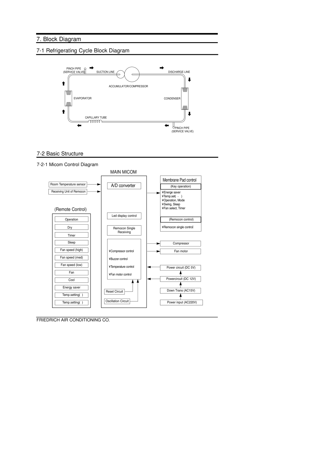
7-1 Refrigerating Cycle Block Diagram
PINCH PIPE | SUCTION LINE | DISCHARGE LINE |
(SERVICE VALVE) | ||
| ACCUMULATOR/COMPRESSOR |
|
EVAPORATOR |
| CONDENSER |
CAPILLARY TUBE
![]() PINCH PIPE (SERVICE VALVE)
PINCH PIPE (SERVICE VALVE)
7-2 Basic Structure
7-2-1 Micom Control Diagram
MAIN MICOM
Room Temperature sensor ![]()
![]() Receiving Unit of Remocon
Receiving Unit of Remocon ![]()
![]()
(Remote Control)
Operation
Dry
Timer
Sleep
Fan speed (high)
Fan speed (med)
Fan speed (low)
Fan
Cool
Energy saver
Temp.setting(↑ )
Temp.setting(↓ )
A/D converter |
Led display control |
Remocon Single |
Receiving |
• Compressor control |
• Buzzer control |
• Temperature control |
• Fan motor control |
Reset Circuit |
Oscillation Circuit |
Membrane Pad control
(Key operation)
• Energe saver
•Temp.set(↑ , ↓ )
•Operation, Mode
•Swing, Sleep
•Fan select, Timer
(Remocon control)
•Remocon single control
Compressor
Fan motor
Power circuit (DC 5V)
Powercircuit (DC 12V)
Down Trans (AC15V)
Power input (AC220V)
FRIEDRICH AIR CONDITIONING CO. |