DEAN MILLIVOLT GAS FRYERS
CHAPTER 2: PARTS LIST
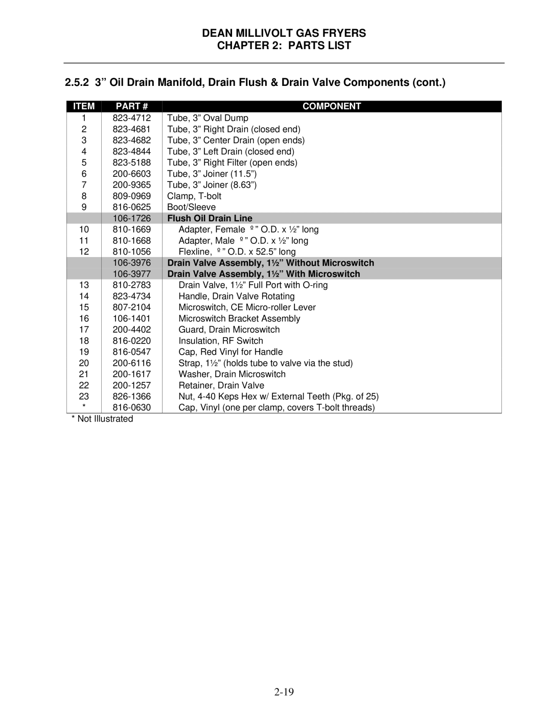
2.5.2 3” Oil Drain Manifold, Drain Flush & Drain Valve Components (cont.)
ITEM | PART # |
1
2
3
4
5
6
7
8
9
![]()
10
11
12
![]()
![]()
13
14
15
16
17
18
19
20
21
22
23
*
*Not Illustrated
COMPONENT
Tube, 3” Oval Dump
Tube, 3” Right Drain (closed end)
Tube, 3” Center Drain (open ends)
Tube, 3” Left Drain (closed end)
Tube, 3” Right Filter (open ends)
Tube, 3” Joiner (11.5”)
Tube, 3” Joiner (8.63”)
Clamp,
Boot/Sleeve
Flush Oil Drain Line
Adapter, Female ⅝” O.D. x ½” long
Adapter, Male ⅝” O.D. x ½” long
Flexline, ⅝” O.D. x 52.5” long
Drain Valve Assembly, 1½” Without Microswitch Drain Valve Assembly, 1½” With Microswitch
Drain Valve, 1½” Full Port with
Cap, Red Vinyl for Handle
Strap, 1½” (holds tube to valve via the stud) Washer, Drain Microswitch
Retainer, Drain Valve
Nut,
