DEAN MILLIVOLT GAS FRYERS
CHAPTER 2: PARTS LIST
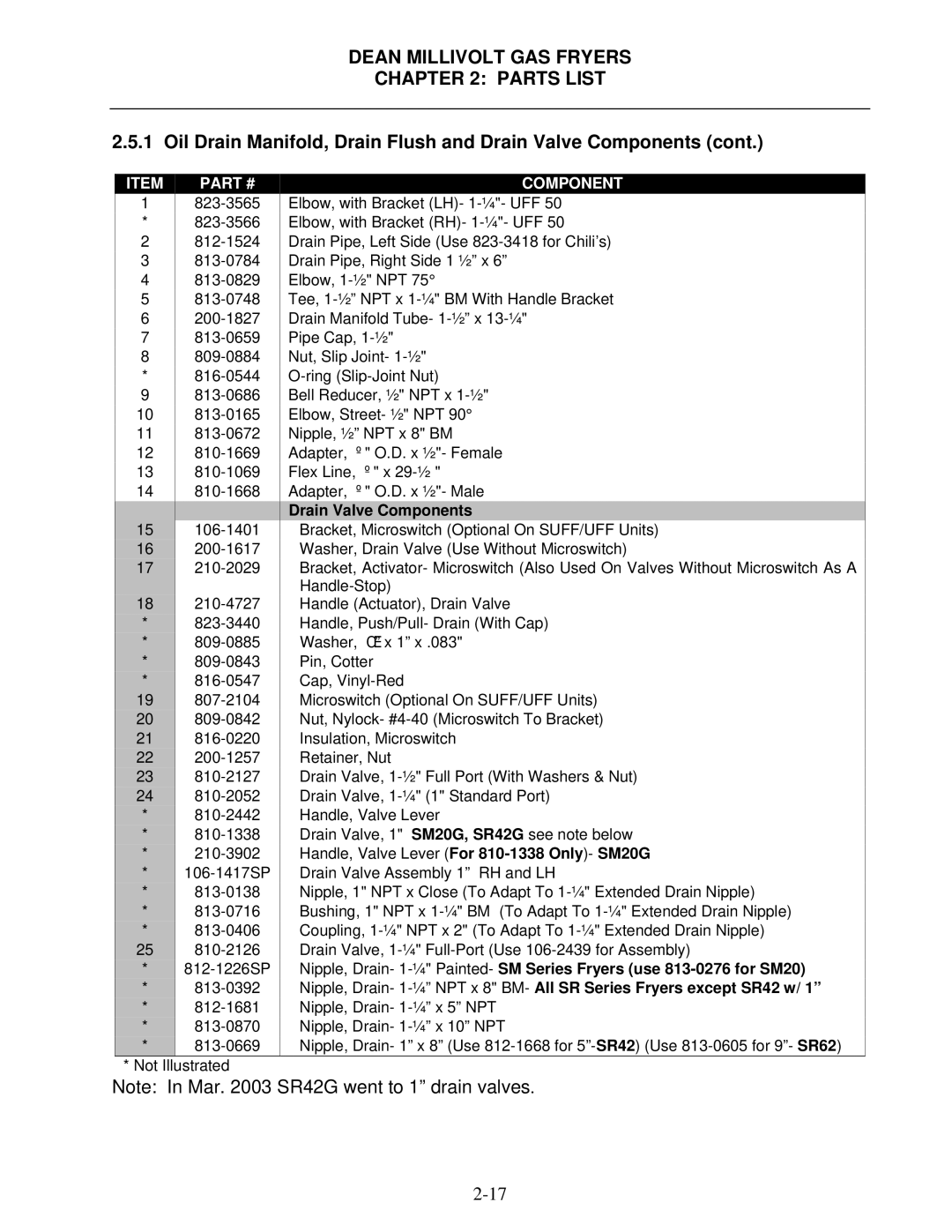
2.5.1 Oil Drain Manifold, Drain Flush and Drain Valve Components (cont.)
ITEM | PART # |
1 |
|
*
2
3
4
5
6
7
8
*
9
10
11
12
13
14
15
16
17
18
*
*
*
*
19
20
21
22
23
24
*
*
*
*
*
*
*
25
*
*
*
*
*
*Not Illustrated
COMPONENT
Elbow, with Bracket (LH)-
Elbow, with Bracket (RH)-
Drain Pipe, Left Side (Use
Drain Pipe, Right Side 1 ½” x 6”
Elbow,
Tee,
Drain Manifold Tube-
Pipe Cap,
Nut, Slip Joint-
Bell Reducer, ½" NPT x
Elbow, Street- ½" NPT 90°
Nipple, ½” NPT x 8" BM
Adapter, ⅝" O.D. x ½"- Female
Flex Line, ⅝" x
Adapter, ⅝" O.D. x ½"- Male
Drain Valve Components
Bracket, Microswitch (Optional On SUFF/UFF Units) Washer, Drain Valve (Use Without Microswitch)
Bracket, Activator- Microswitch (Also Used On Valves Without Microswitch As A
Handle (Actuator), Drain Valve Handle, Push/Pull- Drain (With Cap) Washer, ⅜” x 1” x .083"
Pin, Cotter Cap,
Microswitch (Optional On SUFF/UFF Units)
Nut, Nylock-
Retainer, Nut
Drain Valve,
Handle, Valve Lever
Drain Valve, 1" SM20G, SR42G see note below Handle, Valve Lever (For
Nipple, 1" NPT x Close (To Adapt To
Nipple, Drain-
Nipple, Drain-
Nipple, Drain- 1” x 8” (Use
Note: In Mar. 2003 SR42G went to 1” drain valves.
