
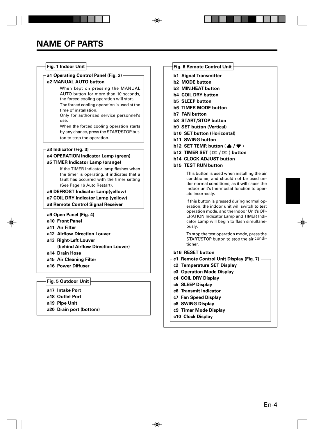
AOU12RLS, Heat & Cool Model (Reverse Cycle), ASU12RLS, AOU9RLS, ASU9RLS specifications
The Fujitsu ASU9RLS, AOU12RLS, ASU12RLS, and AOU9RLS models represent the pinnacle of advanced climate control solutions, combining energy efficiency with exceptional performance in both heating and cooling applications. These reverse cycle air conditioning systems are designed to cater to a wide range of residential and light commercial environments, ensuring comfort throughout the year.One of the standout features of these models is the inverter technology that optimizes energy consumption. By continuously adjusting the compressor speed to maintain the desired temperature, these units minimize fluctuations, thereby enhancing comfort and reducing energy bills. This technology also leads to quieter operation, making it an excellent choice for homes and offices where noise level is a concern.
The ASU series offers a sleek and modern design, allowing it to blend seamlessly into various interior decors. User-friendly remote controls and smart sensors enable easy management and monitoring of temperature settings, ensuring users can maintain their ideal comfort levels with minimal effort. Additionally, the models are equipped with a range of air filtration systems, including washable filters that effectively capture dust and allergens, contributing to healthier indoor air quality.
Fujitsu's commitment to energy efficiency is further reflected in the high star ratings for these models, which comply with the latest environmental standards. The reverse cycle capability not only provides effective cooling during the hotter months but also ensures efficient heating when temperatures drop, making these models versatile and cost-effective.
Durability is another hallmark of Fujitsu's design philosophy. The units are built with high-quality materials, ensuring longevity and resistance to various environmental conditions. Advanced technology is also used to ensure that the outdoor units can operate effectively even in extreme weather conditions, providing reliable performance year-round.
In summary, the Fujitsu ASU9RLS, AOU12RLS, ASU12RLS, and AOU9RLS models offer an ideal combination of energy efficiency, exceptional performance, and advanced technology. Their inverter systems, stylish design, effective filtration, and durability make them an excellent choice for anyone looking to enhance their indoor climate control while maintaining energy efficiency. Whether for a cozy home or a productive office space, these reverse cycle units are engineered to deliver comfort and reliability in any season.