Interfaces and connectors | Features |
3.7Interfaces and connectors
1
22 ![]()
![]()
21![]()
![]() 20
20![]()
![]()
![]()
![]()
2
3
19
|
|
| CPU 2 |
|
18 |
|
| CPU Fan2 |
|
17 | Fan 2 | System | Fan 1 | System |
16 | Fan 4 | System | Fan 3 | System |
| ||||
| 15 |
| 141312 11 |
|
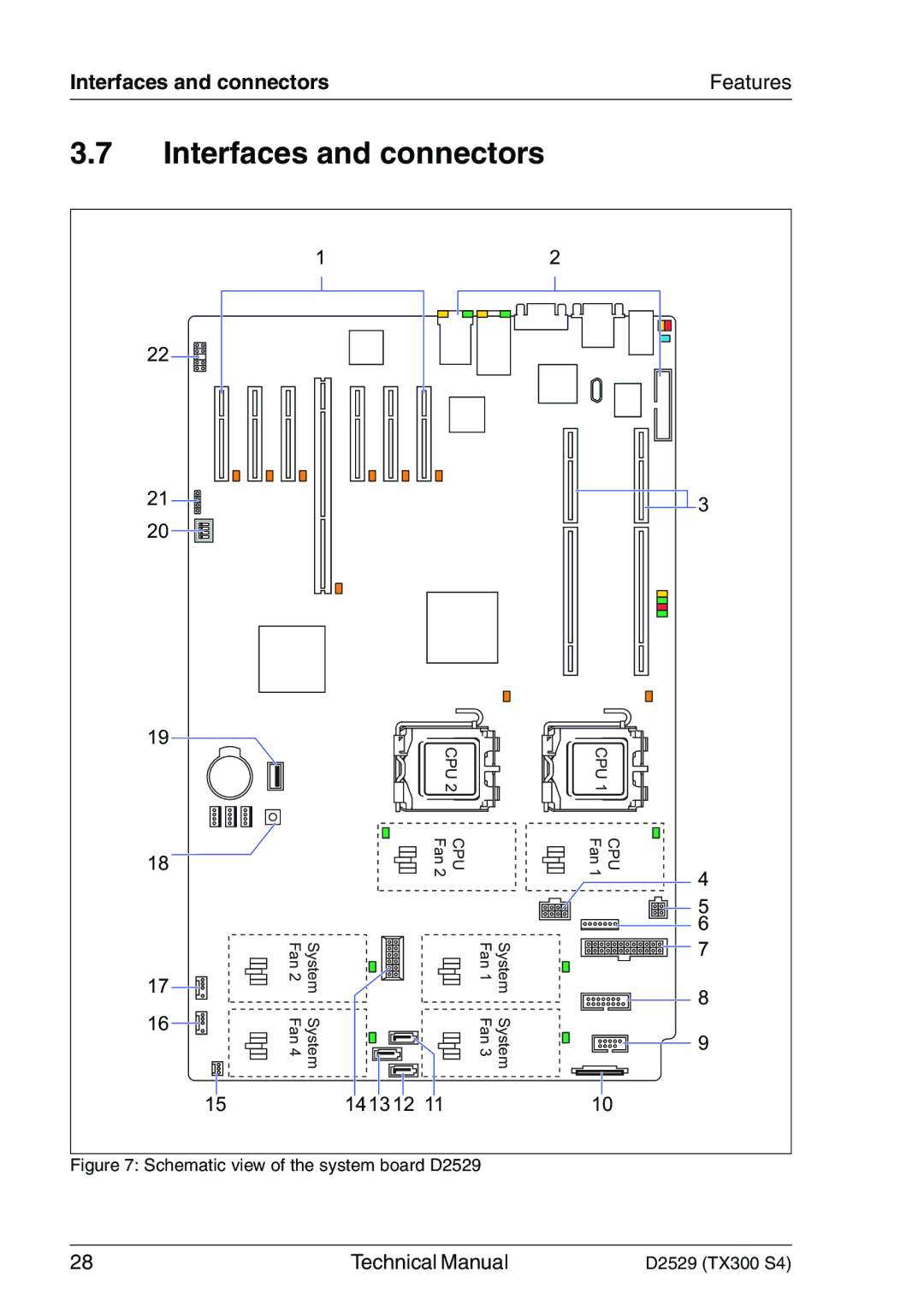
Figure 7: Schematic view of the system board D2529
CPU 1
Fan CPU 1 4
![]()
![]()
![]()
![]() 5 6
5 6
![]() 7
7
8
9
10
28 | Technical Manual | D2529 (TX300 S4) |
