Change even page title here
Chapter 7 Connectors
7.4UART (X4)
One
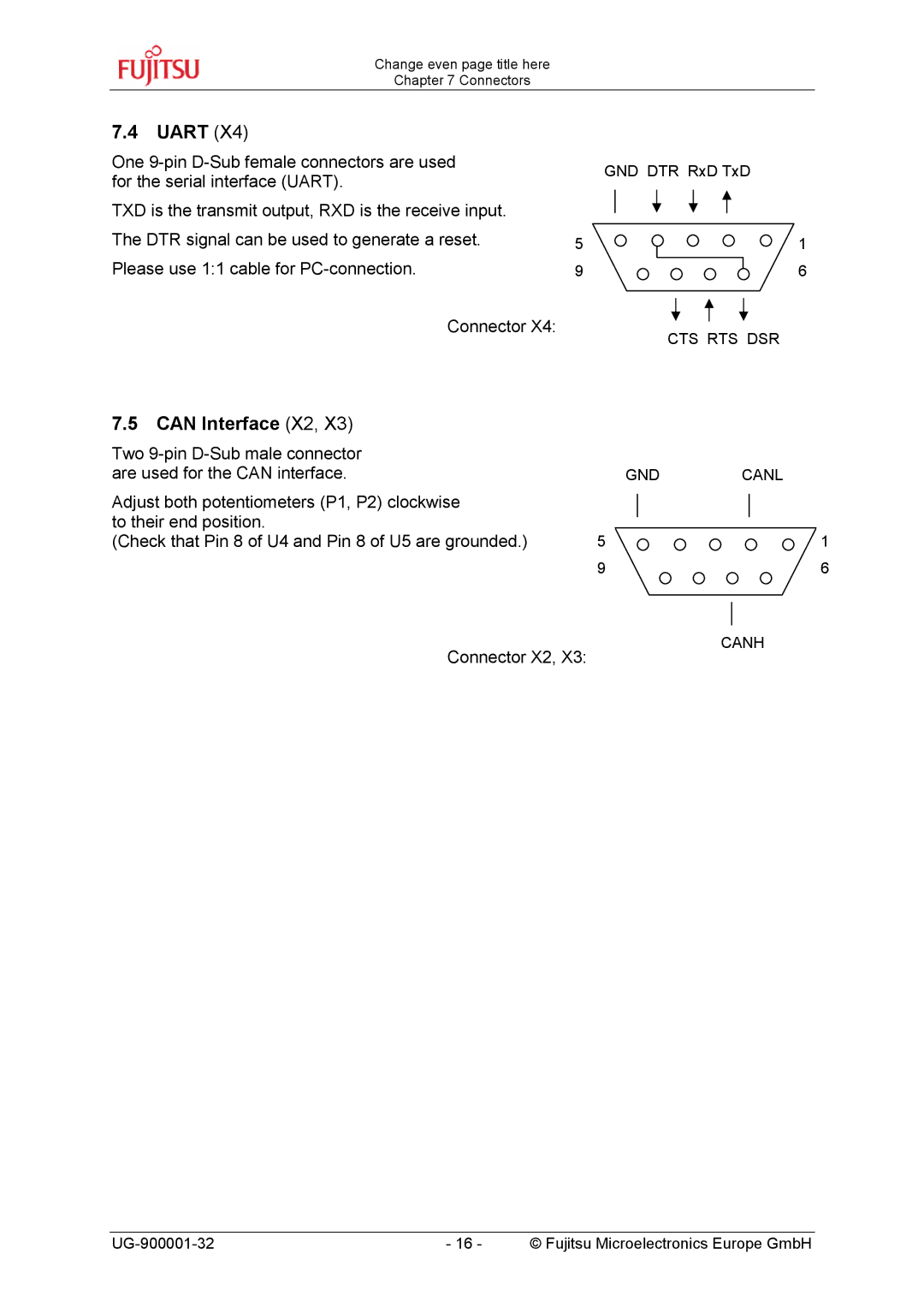
TXD is the transmit output, RXD is the receive input. The DTR signal can be used to generate a reset. Please use 1:1 cable for
Connector X4:
| GND DTR RxD TxD |
5 | 1 |
9 | 6 |
CTS RTS DSR
7.5CAN Interface (X2, X3)
Two |
|
|
|
|
|
|
are used for the CAN interface. |
| GND | CANL | |||
Adjust both potentiometers (P1, P2) clockwise |
|
|
|
|
|
|
|
|
|
|
|
| |
to their end position. |
|
|
|
|
|
|
|
|
|
|
|
| |
(Check that Pin 8 of U4 and Pin 8 of U5 are grounded.) | 5 |
|
|
| 1 | |
| 9 |
|
|
| 6 | |
|
|
|
|
|
|
|
Connector X2, X3:
CANH
- 16 - | © Fujitsu Microelectronics Europe GmbH |
