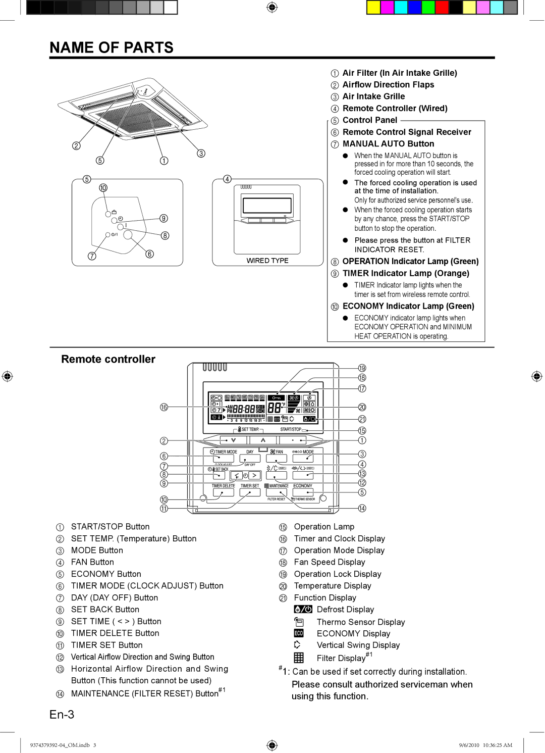
NAME OF PARTS
WIRED TYPE
1Air Filter (In Air Intake Grille)
2 Airflow Direction Flaps
3 Air Intake Grille
4 Remote Controller (Wired)
5 Control Panel
6 Remote Control Signal Receiver
7 MANUAL AUTO Button
●When the MANUAL AUTO button is pressed in for more than 10 seconds, the forced cooling operation will start.
●The forced cooling operation is used at the time of installation.
Only for authorized service personnel's use.
●When the forced cooling operation starts by any chance, press the START/STOP button to stop the operation.
●Please press the button at FILTER INDICATOR RESET.
8OPERATION Indicator Lamp (Green)
9 TIMER Indicator Lamp (Orange)
●TIMER Indicator lamp lights when the timer is set from wireless remote control.
0ECONOMY Indicator Lamp (Green)
●ECONOMY indicator lamp lights when ECONOMY OPERATION and MINIMUM HEAT OPERATION is operating.
Remote controller
| I | |
| H | |
| G | |
F | J | |
| K | |
| E | |
2 | 1 | |
6 | 3 | |
4 | ||
7 | ||
8 | C | |
9 | B | |
0 | 5 | |
| ||
A | D |
1START/STOP Button
2SET TEMP. (Temperature) Button
3 MODE Button
4 FAN Button
5 ECONOMY Button
6 TIMER MODE (CLOCK ADJUST) Button
7 DAY (DAY OFF) Button
8 SET BACK Button
9 SET TIME ( < > ) Button
0 TIMER DELETE Button A TIMER SET Button
B Vertical Airflow Direction and Swing Button
C Horizontal Airflow Direction and Swing Button (This function cannot be used)
D MAINTENANCE (FILTER RESET) Button#1
EOperation Lamp
FTimer and Clock Display G Operation Mode Display H Fan Speed Display
I Operation Lock Display J Temperature Display K Function Display
![]() Defrost Display
Defrost Display
Thermo Sensor Display
ECONOMY Display
Vertical Swing Display
Filter Display#1
#1: Can be used if set correctly during installation. Please consult authorized serviceman when using this function.
9/6/2010 10:36:25 AM
