6External speaker output terminal (EXT SP)
Connect this terminal to the optionally available speaker.
When connecting a cable, attach a ferrite core to the cable. (See P.
7 | Audio1 input terminal (AUDIO1 INPUT) |
|
8 | Audio2 input terminal (AUDIO2 INPUT) |
|
9 | Audio3 input terminal (AUDIO3 INPUT) |
|
| Connect this terminal to the sound output terminal of your VCR, etc. (See | ut.) |
0Component video input terminal (VIDEO3 INPUT)
Connect this terminal to the component video output (color difference output) terminal of your HDTV unit or DVD player.
A
Connect this terminal to the
BVideo input terminal (VIDEO1 INPUT)
Connect this terminal to the video output terminal of your VCR.
CComponent video input terminal (VIDEO4 INPUT)
Connect this terminal to the component video output (color difference output) terminal of your HDTV unit or DVD player.
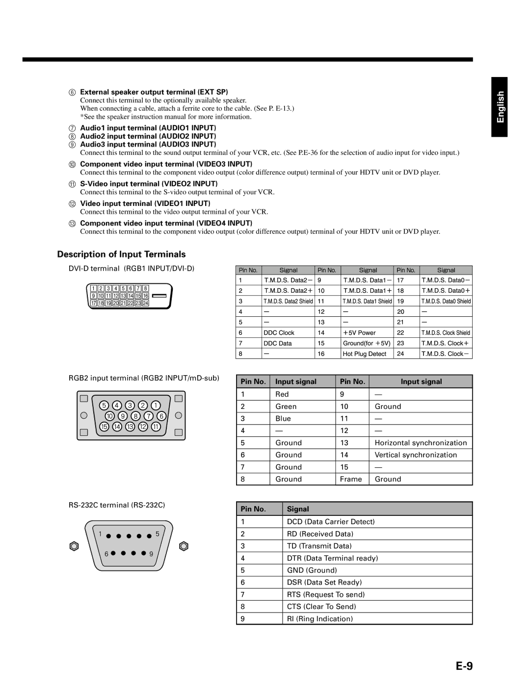
Description of Input Terminals
English
RGB2 input terminal (RGB2
Pin No. | Input signal | Pin No. | Input signal |
1 | Red | 9 | — |
|
|
|
|
2 | Green | 10 | Ground |
|
|
|
|
3 | Blue | 11 | — |
|
|
|
|
4 | — | 12 | — |
|
|
|
|
5 | Ground | 13 | Horizontal synchronization |
|
|
|
|
6 | Ground | 14 | Vertical synchronization |
|
|
|
|
7 | Ground | 15 | — |
|
|
|
|
8 | Ground | Frame | Ground |
|
|
|
|
|
|
|
|
Pin No. | Signal |
|
|
|
|
|
|
1DCD (Data Carrier Detect)
2RD (Received Data)
3TD (Transmit Data)
4DTR (Data Terminal ready)
5GND (Ground)
6DSR (Data Set Ready)
7RTS (Request To send)
8CTS (Clear To Send)
9RI (Ring Indication)