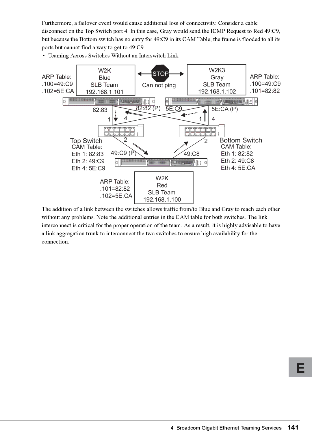
Furthermore, a failover event would cause additional loss of connectivity. Consider a cable disconnect on the Top Switch port 4. In this case, Gray would send the ICMP Request to Red 49:C9, but because the Bottom switch has no entry for 49:C9 in its CAM Table, the frame is flooded to all its ports but cannot find a way to get to 49:C9.
• Teaming Across Switches Without an Interswitch Link
ARP Table: | W2K |
|
Blue |
| |
.100=49:C9 | SLB Team |
|
.102=5E:CA | 192.168.1.101 |
|
| 82:83 |
|
| 1 | 4 |
STOP
Can not ping
82:82 (P) 5E:C9
W2K3
Gray
SLB Team 192.168.1.102
![]() 5E:CA (P)
5E:CA (P)
1 4
ARP Table:
.100=49:C9
.101=82:82
Top Switch | 2 | 2 |
CAM Table: |
| |
Eth 1: 82:83 49:C9 (P) | 49:C8 | |
Eth 2: 49:C9 |
| |
Eth 4: 5E:C9 |
| |
ARP Table: | W2K | |
Red | ||
.101=82:82 | ||
SLB Team | ||
.102=5E:CA | ||
192.168.1.100 | ||
|
Bottom Switch
CAM Table:
Eth 1: 82:82
Eth 2: 49:C8
Eth 4: 5E:CA
The addition of a link between the switches allows traffic from/to Blue and Gray to reach each other without any problems. Note the additional entries in the CAM table for both switches. The link interconnect is critical for the proper operation of the team. As a result, it is highly advisable to have a link aggregation trunk to interconnect the two switches to ensure high availability for the connection.
E
