Color Scanning Sonar
00080807301
Safety Instructions
Table of Contents
Iii
Self Tests
Foreword
System Configuration
Control Description
Main panel control description
Main Panel
Control Function
END
Sub Panel
Sub Panel 2 data setting window
Main Setting Description Normal
Main Setting Description Normal Sub Range
+ +
Remote Control Box
Adjusting Screen Brilliance, Control Panel Backlighting
Turning the Power On/Off
Operational Overview
Lowering the Transducer
Display mode description
Selecting a Display Mode
Seabed echo and tilt angle
Setting the Tilt Angle
Selecting a Display Range
Points to consider
How to discriminate fish echoes from the seabed
Tilt angle and sea surface reflections
Tilt angle for surface fish
Tilt angle and beam coverage
Suitable tilt angle
Measuring Range and Bearing to a Target
Adjusting the Gain
This page is intentionally left blank
Eliminating Unwanted Feeble Echoes
Fine Tuning the Picture
How to adjust TVG
Page
Pulselength data setting window TVG TX, PL
AGC data setting window SIGNAL, Signal
2AGC data setting window SIGNAL, Signal Process
Suppressing Seabed Tail
Identifying noise source
Data setting window TVGTX, Output
Rejecting Sonar Interference and Noise
Cycle
Changing Tx cycle data setting window Tvgtx
Noise limiter data setting window SIGNAL, Signal Process
Setting F-shift data setting window Sonrbeam
Marks and Data
Marks, Data and Display Mode
Normal display mode
Echo sounder combination display
Normal display mode w/text
History display
Permanently Displayed Marks and Data
Erasable Marks and Data
Bearing marker Range marker
Mark Description
Range R Auto Tilt ± Auto Scan ± Gain Brill TVG TVG DIM
This page is intentionally left blank
User Menu Operation
Menu Overview
User Menu Hist DSP/GRPH
Menu screen location and display mode
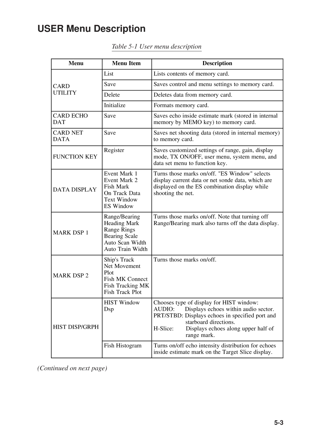
User menu description
User Menu Description
Current VEC
System menu can be displayed by pressing Menu + c
System Menu Description
Menu Description
ES/NET REC
Data SET menu can be display by pressing Menu + d
Data SET Menu Description
Menu
NET Shoot
Init SET/TEST menu can be displayed by pressing Menu + on
Init SET/TEST Menu Description
Defaults
Programming the Function Keys
Function Keys
Replaying a Function Key
Function Key Fine Tuning
Replaying Function Key Settings from a Memory Card
Saving Function Key Settings to a Memory Card
This page is intentionally left blank
Finding Fish School Center
How to find fish school center
Advanced Level Operation
Tracking a fish school
Tracking a Fish School target lock
Erasing target lock mark
Choosing target lock mode
Target lock mark appearance
Target lock and tilt angle
Tracking target lock mark
System Menu Target Lock
Setting target lock conditions
Description of target lock items
Detecting Fish Schools Aurally
How to set the fish alarm zone
Fish Alarm
Relocating Fish School for Easy Observation
How to relocate fish schools
Estimate marks and their data
Comparing of Fish School Concentration
Measuring Fish School Speed
How to measure fish speed
10 Event marks
Event Mark
Erasing an event mark
Entering an event mark
12 True motion display
True Motion Display
13 Net location mark
Plotting Net Location Mark
14 Net behavior
Observing Net Behavior
Reducing Sea Surface Reflections
Boosting Tx Power
This page is intentionally left blank
Port/Starboard display
PORT/STARBOARD, Horizontal Slice Displays
Horizontal slice display
Horizontal slice display
Initializing Memory Cards
SAVING, Replaying Picture
Transferring Echo Data from Internal Memory to Memory Card
Saving the Picture
Saving Net Shooting Data
Net shooting data contents
How net shooting data is saved
Transferring net shooting data to memory card
Replaying Saved Data
Deleting Memory Card Contents
Turning marks on/off through the user menu
Turning marks on/off through the data setting window
Turning MARKS, Data ON/OFF
This page is intentionally left blank
Seabed Echoes
Interpreting the Display
Midwater, bottom fish Tilt angle 30 or more
Fish Schools
Wake
Sea Surface Reflections
Noise and Interference
False Echo by Sidelobe
Unretracted Transducer Warning
Overvoltage Warning
Raise/Lower Control Box of the Hull Unit
Self Tests
Continuous test
Self Test Description
Single test
Color test
Panel test
SIO test
Gray test
Interface unit CS-120A, cover opened
Interface Unit CS-120A Self Test
This page is intentionally left blank
Selection of Data on Interface Unit CS-120A
Input Data Selection
How to set net sonde transmitter distances
Setting Distances Between Net Sonde Transmitters
Maintenance
Zinc block near the transducer must be replaced yearly
Hull Unit Maintenance
Replacement of Fuse, Memory Card Battery
15-4
User Menu
Menu Tree
Data SET Menu
Init SET/TEST Menu
System Menu
Previous
This page is intentionally left blank
General
Specifications
Display
Environmental Condition
12-7
Index