ADVANCED LEVEL OPERATION
Finding Fish School Center
When you want to find the center depth of a fish school, use the auto tilt function, which automatically scans the tilt angle within the selected width.
Range (m) | Width (1) | Width (2) | Width (3) | Period |
|
|
|
|
|
75, 100 | 10° | 16° | 20° | every 6 transmissions |
150, 200 | " | " | " | every 4 transmissions |
300, 400 | " | " | " | every 2 transmissions |
500, 600 | 8° | " | " | " |
800 | 6° | 12° | 16° | " |
1000 | 4° | 8° | 12° | " |
more than 1200 | 2° | 4° | 6° | " |
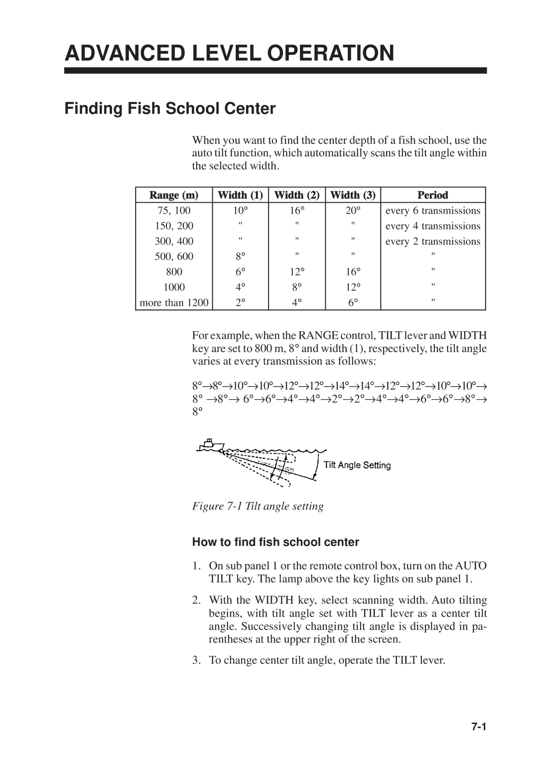
For example, when the RANGE control, TILT lever and WIDTH key are set to 800 m, 8° and width (1), respectively, the tilt angle varies at every transmission as follows:
8°→8°→10°→10°→12°→12°→14°→14°→12°→12°→10°→10°→ 8° →8°→ 6°→6°→4°→4°→2°→2°→4°→4°→6°→6°→8°→ 8°
Figure 7-1 Tilt angle setting
How to find fish school center
1.On sub panel 1 or the remote control box, turn on the AUTO TILT key. The lamp above the key lights on sub panel 1.
2.With the WIDTH key, select scanning width. Auto tilting begins, with tilt angle set with TILT lever as a center tilt angle. Successively changing tilt angle is displayed in pa- rentheses at the upper right of the screen.
3.To change center tilt angle, operate the TILT lever.