Installation manual
00014869015
Safety Instructions
Use only the specified power cables
Iii
System Configuration
Name Type Code No Qty Remarks
Standard supply
Name Type Code No Remarks
Optional equipment
This page is intentionally left blank
Mounting considerations
Antenna Unit
Siting
Mounting
Mounting precaution for S-band antenna unit
Installation precaution for S-band antenna unit
Assembling the antenna unit
Be sure to remove the guide pins after fixing the radiator
Attachment of lifting fixtures, collar and ropes
How to hoist the antenna unit
Fastening the antenna unit to the mounting platform
Installation of reinforcement ribs
Mounting the antenna unit
Mounting procedure
Monitor Unit
Flush mounting
Desktop mounting
Contents of desktop mounting kit FP03-09820
Attaching hand grips
Fixing with KB keyboard fixing plate
Control Unit
Mounting dimensions for control unit RCU-014
Mounting dimensions for control unit RCU-015/RCU-016
Fixing without KB fixing plate
Name Type Qty
Contents of flush mount kit for RCU-014/015/016
Control unit RCU-014, inside view
Connecting RCU-016 in series with RCU-014
Changing cable entrance on control unit RCU-015/RCU-016
Changing the cable entrance on control unit RCU-015/RCU-016
Processor Unit
Mounting dimensions for processor unit
Mounting dimensions for power supply unit
Power Supply Unit
Wiring Overview
Wiring
Fabricating signal cable RW-9600 and HV cable TYPCY-1.5
Fabricating signal cable RW-9600
Antenna unit, front view
Armor Gasket Signal cable Flat washer Flat washer Gland nut
How to fabricate HV cable TYPCY-1.5
How to wire Wago connector
How to fabricate power cable TYPCY-2.5
Fabricating the power cable TYPCY-2.5
Antenna unit, left-side view
Passing flat washer, etc. onto HV cable
Fabricating power cable DPYC-2.5
Fabricating the power cable DPYC-2.5
Monitor Unit for FAR-2167DS
Monitor unit MU-201CR, rear view
Processor Unit
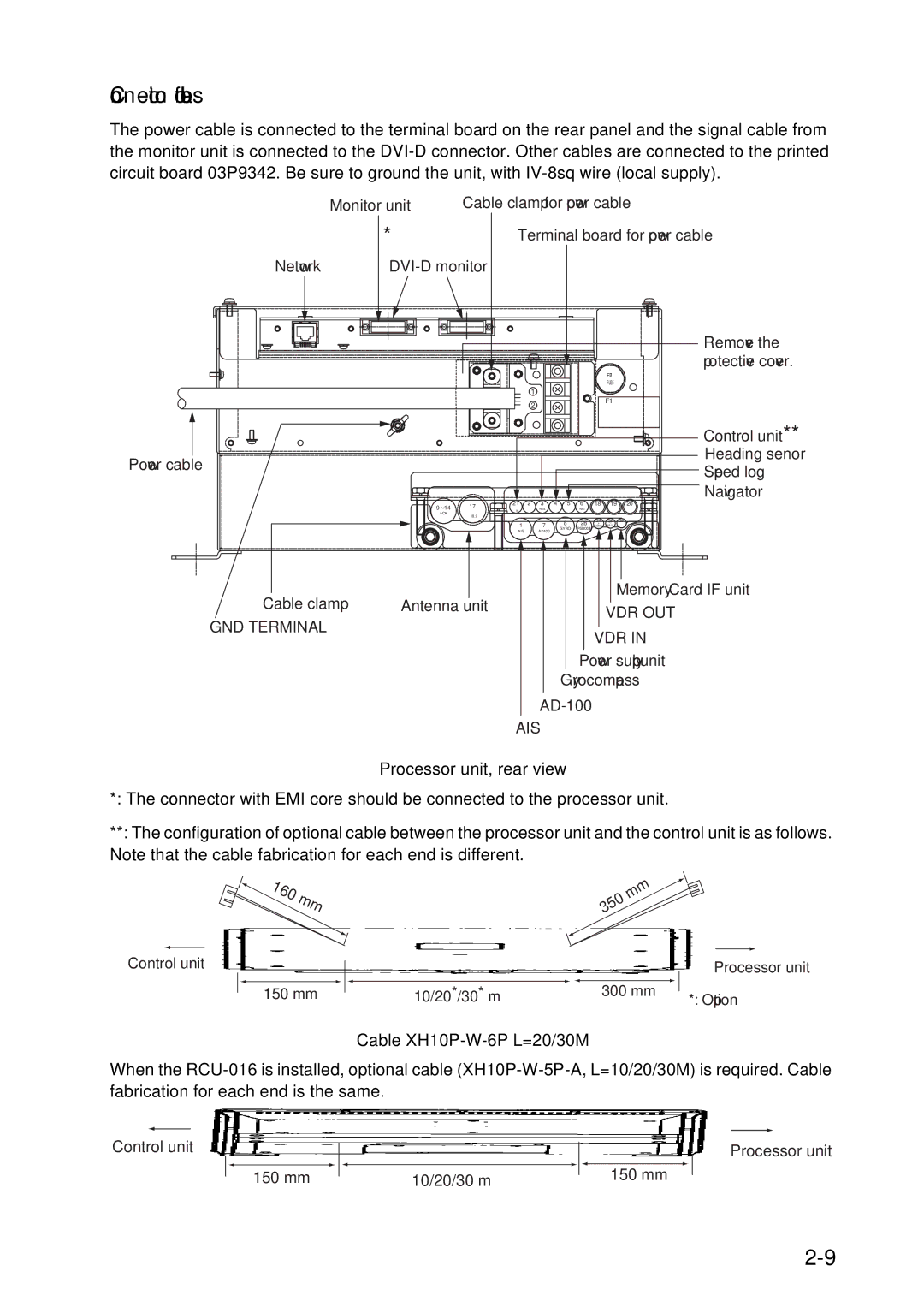
Connection of cables
Processor unit, rear view
Cable XH10P-W-6P L=20/30M
Location of connectors inside the processor unit
Location of connectors
Power cable TPYC-1.5
Signal cable RW-9600 Between antenna unit and processor unit
Port Conventional remote display FAR-2167DS
Connection of Sub-display
Power supply unit, inside view
Fabricating cable connected to terminal TB1, TB2, TB3
Terminal TB1 cable DPYC-2.5
Armor
Power supply Fuse Jumper connector P108
Changing AC Power Specification
Processor unit
Processor unit, inside view
How to adjust the overvoltage detection circuit
Power Fuse Jumper connector P8
Power supply unit
How to adjust the overvoltage detection circuit
Initializing Tuning
Adjustments
Heading alignment
Heading Alignment
For Control Unit RCU-015
For Control Unit RCU-014
Initialize menu
Echo ADJ menu
How to access the Initialize Menu with Control Unit RCU-015
Examples of correct and incorrect sweep timings
Adjusting Sweep Timing
Suppressing Main Bang
Echo menu setting
Other Settings
Scanner menu
Blind Sector 1 and Blind Sector
ANT SW and ANT Stopped
Installation menu
Radar no and Radar Posn
On Time and TX Time
OWN Ship Info menu
LENGTH/WIDTH, Scanner Posn and SUB Scanner Posn
GPS 1 ANT Posn and GPS 2 ANT Posn
Arpa Preset menu
ARP W/O Gyro Not shown on IMO radar
ARP-related menus
ANT Select
Other menu
EAV w/o Gyro
Other menu
This page intentionally left blank
Gyro Converter GC-10
Installing the Gyro Converter board
Fixing Gyro Converter board inside the processor unit
Wiring Wago connector
Connecting connector assemblies inside processor unit
Attaching plastic cover for Gyro Converter board
DIP switch, jumper wire settings
Connection of external power supply
Default setting
Connection of external power supply to Gyro Converter board
JP1
JP1 JP2 JP3 JP4 JP5
Setting method 2 by make and model of gyrocompass
Gyro Converter board
64P1106
HDG menu
Setting the heading readout on the radar display
Memory Card Interface Unit
Flush mounting dimensions for memory card interface unit
Desktop mount
Connections
One memory card if unit and one processor unit
One memory card if unit and multiple processor units
Type Code No Contents
DVI-RGB Conversion Kit
How to wire the DVI-RBG conversion board
Processor unit bottom chassis
Processor unit, side view
Connecting wires to the housing
DVI-RGB
BNC Connector Converter
Data Specifications Contents Remarks
Input
Output
IEC 61162 output sentence
IEC 61162 input sentence and priority
Sentence and order of priority
Sentence
70+6
���1������
Packing List
�7�6�.�+�0� +26+10�%1&�
52��������
427����
52��������
257����
#%���8
���.������
���.������
���.������
��������������
�����
GC-10
$�40��#
14/Feb/2011 Y.NISHIYAMA
Page
May 1707 R.Esumi
Sep/2010 Y.NISHIYAMA
Page
Jan.1808 R.Esumi
Apr.2307 R.Esumi
Apr.2307 R.Esumi
Apr.2307 R.Esumi
Apr.2307 R.Esumi
Apr.2307 R.Esumi
Page
Page
Page
Page
Page
Page
Page
Page
Page
Interconnection Diagram