2.4 Processor Unit
Four cables are terminated at the processor unit: the antenna unit cable, monitor unit cable (FAR- 2167DS only), control unit cable and the power cable. Cables other than the power cable come with a connector preattached to them. Fabricate the power cable as below.
Note: Pass the AC line through a
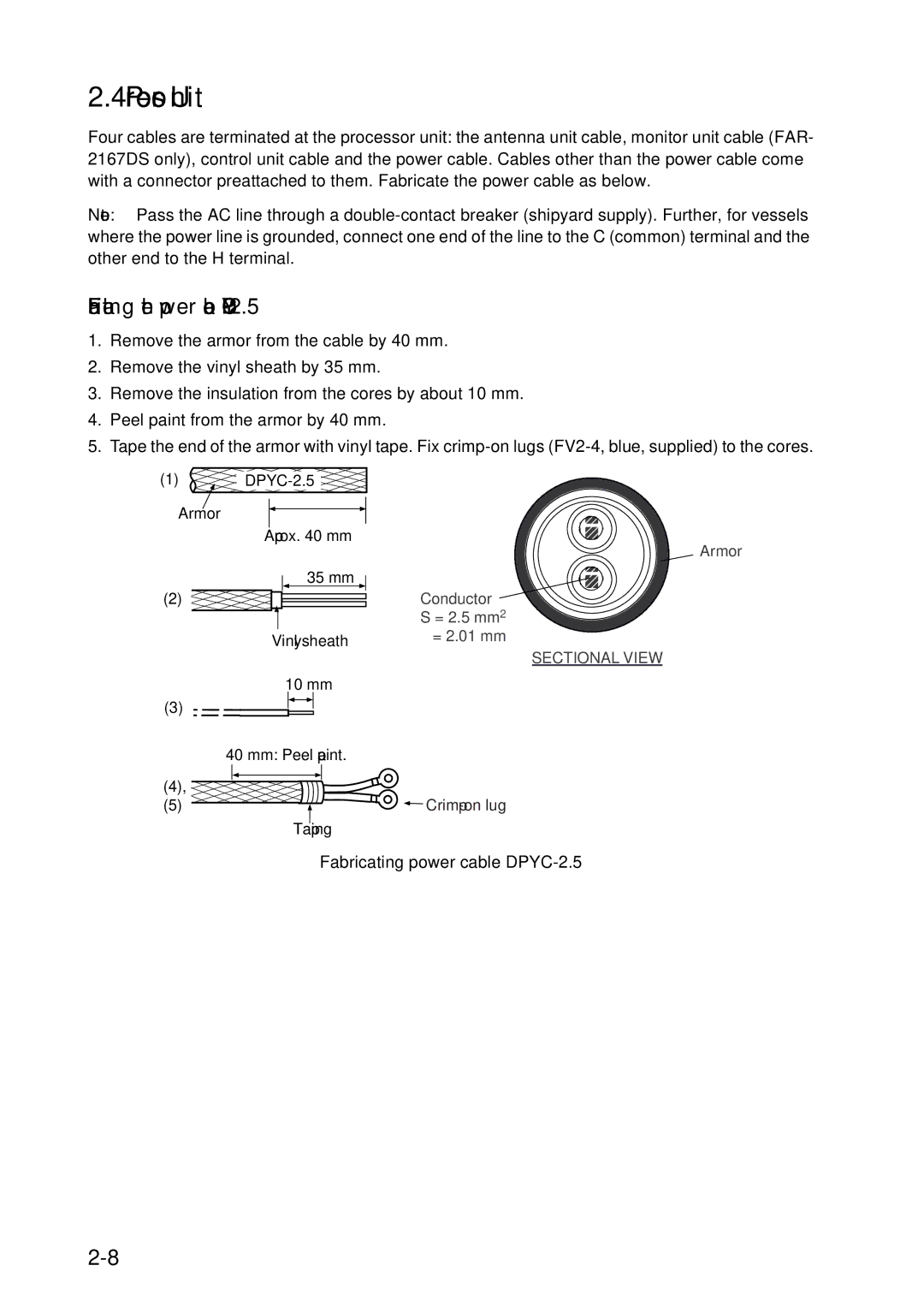
Fabricating the power cable DPYC-2.5
1.Remove the armor from the cable by 40 mm.
2.Remove the vinyl sheath by 35 mm.
3.Remove the insulation from the cores by about 10 mm.
4.Peel paint from the armor by 40 mm.
5.Tape the end of the armor with vinyl tape. Fix
(1) | |
Armor |
|
Approx. 40 mm
35 mm
(2)![]()
![]()
Vinyl sheath
10 mm
(3)
40 mm: Peel paint.
(4),
(5) ![]()
![]() Taping
Taping
Armor
Conductor S = 2.5 mm2 φ = 2.01 mm
SECTIONAL VIEW
![]()
![]()