1. INSTALLATION
Wiring
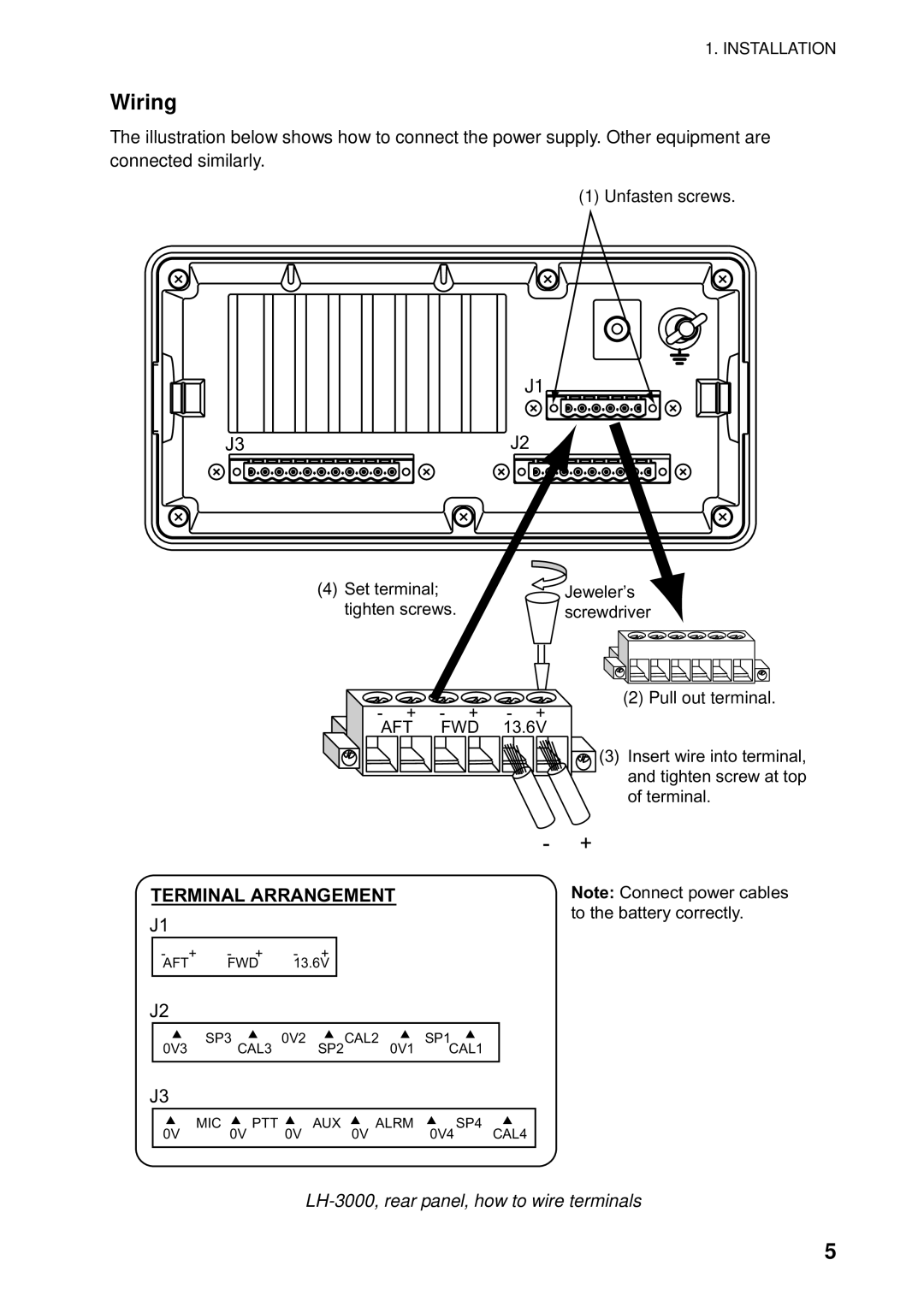
The illustration below shows how to connect the power supply. Other equipment are connected similarly.
(1) Unfasten screws.
J1
J3 | J2 |
(4)Set terminal; tighten screws.
-+ - +
AFT FWD
![]() Jeweler’s screwdriver
Jeweler’s screwdriver
(2) Pull out terminal.
-+
13.6V
![]() (3) Insert wire into terminal, and tighten screw at top of terminal.
(3) Insert wire into terminal, and tighten screw at top of terminal.
|
|
|
|
|
|
| - + | ||
TERMINAL ARRANGEMENT |
|
|
| Note: Connect power cables | |||||
J1 |
|
|
|
|
|
|
| to the battery correctly. | |
|
|
|
|
|
|
|
| ||
| - + | - + | - + |
|
|
|
|
|
|
| AFT | FWD | 13.6V |
|
|
|
|
|
|
J2 |
|
|
|
|
|
|
|
| |
| SP3 | 0V2 | CAL2 | SP1 |
|
|
| ||
| 0V3 | CAL3 | SP2 | 0V1 | CAL1 |
|
|
| |
J3 |
|
|
|
|
|
|
|
| |
| MIC | PTT | AUX | ALRM | SP4 | CAL4 |
| ||
| 0V | 0V | 0V | 0V | 0V4 |
| |||
LH-3000, rear panel, how to wire terminals
5