2.0 Tool List
Listed below are the tools required to assemble an EVA array:
1.Phillips #2 screwdriver (for attaching cosmetic end panels).
2.6-mm Allen (hex) wrench (for attaching tie plates and assembling grids).
3.3/16-inch flat-blade screwdriver (for attaching signal wires to input-panel connectors).
3.0Designing an EVA Array
3.1Applications for Which EVA Arrays Are Most Appropriate
The total included vertical angles of the EVA modules in side view (6° for long throw and 20° for short throw) were determined after making many array simulations with the EVA Design Assistant (EVADA™) software (described in some detail below). Optimum maximum throw distance for uniform front-to-back coverage is 100 ft ±25 ft.
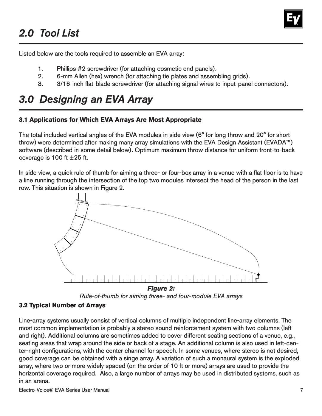
In side view, a quick rule of thumb for aiming a three- or four-box array in a venue with a flat floor is to have a line running through the intersection of the top two modules intersect the head of the person in the last row. This situation is shown in Figure 2.
Figure 2:
Rule-of-thumb for aiming three- and four-module EVA arrays
3.2 Typical Number of Arrays
Line-array systems usually consist of vertical columns of multiple independent line-array elements. The most common implementation is probably a stereo sound reinforcement system with two columns (left and right). Additional columns are sometimes added to cover different seating sections of a venue, e.g., seating areas that wrap around the side or back of a stage. An additional column is also used in left-cen- ter-right configurations, with the center channel for speech. In some venues, where stereo is not desired, good coverage can be obtained with a singe array. A variation of such a monaural system is the exploded array, where two or more widely spaced (on the order of 10 ft or more) arrays are used to provide the horizontal coverage required. Also, a large number of arrays may be used in distributed systems, such as in an arena.
Electro-Voice® EVA Series User Manual | 7 |