NMEA 0183 Connections
The Autopilot does not need to connect to a GPS for the autopilot to work, but if you want to use waypoint steering you must connect to a GPS and set North see page 29. The Autopilot will accept NMEA input from two GPS units and transmit NMEA to one receiving device. Only one of the GPS inputs is used for steering control at a time. Selection of the controlling GPS is made through the NMEA source selection [code 34] (see pages
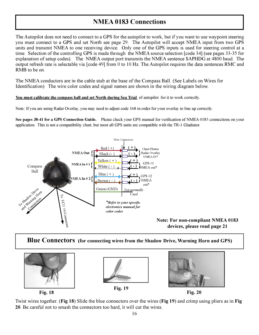
The NMEA conductors are in the cable stub at the base of the Compass Ball. (See Labels on Wires for Identification) The wire color codes and signal names are shown in the wiring diagram below.
You must calibrate the compass ball and set North during Sea Trial of autopilot for it to work correctly.
Note: If you are using Radar Overlay, you may need to adjust code 168 in order for your overlay to line up correctly.
See pages
|
| Compass | ||
|
|
| Ball | |
|
|
| Drive | |
| Shadow |
| Horn | |
To |
|
| ||
| Warning |
| ||
and | Connectors | |||
| Wire Connectors |
| ||
NMEA Out { | Red ( +) | ( + ) | Chart Plotter | |
Black (- ) | ( - ) | }Radar Overlay | ||
| Yellow ( + ) | ( + ) | NMEA IN* | |
NMEA In # 1{ | GPS #1 | |||
|
| |||
White ( - ) | ( - ) }NMEA out* | |||
NMEA In # 2{ | Blue ( + ) | ( + ) | GPS #2 | |
Brown ( - ) | ( - ) | }NMEA | ||
| Green (GND) |
| out* | |
| Not normally | |||
To |
| Used |
| |
|
|
| ||
ECU | *Refer to your specific | |||
#4 | electronics manual for | |||
color codes |
|
| ||
Connector |
|
| Note: For | |
|
|
| ||
devices, please read page 21
Blue Connectors (for connecting wires from the Shadow Drive, Warning Horn and GPS)
Fig. 18 | Fig. 19 | Fig. 20 |
|
Twist wires together. (Fig 18) Slide the blue connectors over the wires (Fig 19) and crimp using pliers as in Fig 20. Be careful not to smash the connectors too hard, it will cut the wires.
16