Installation of Compass Ball
The Compass Ball connects to #4 on the ECU. The Compass needs to be mounted in the front 1/2 of the boat. The Compass ball contains a fluxgate compass which is sensitive to magnetic disturbances, be aware of what is around it before mounting it permanently. Keep such items as, radio speakers, anchors, air ride seats, windshield wiper motors, tool boxes, fire extinguisher, and the autopilot pump motor at least 24” away from the Compass Ball. These items will cause the Compass Ball to malfunction. The Compass Ball contains a Fluxgate Compass and Gyro; it’s important that it is orientated correctly in the bracket. Place the ball in the bracket as to allow the wires to come straight down as pictured in Fig.17.
Fig 13
Fig. 14
Fig.17
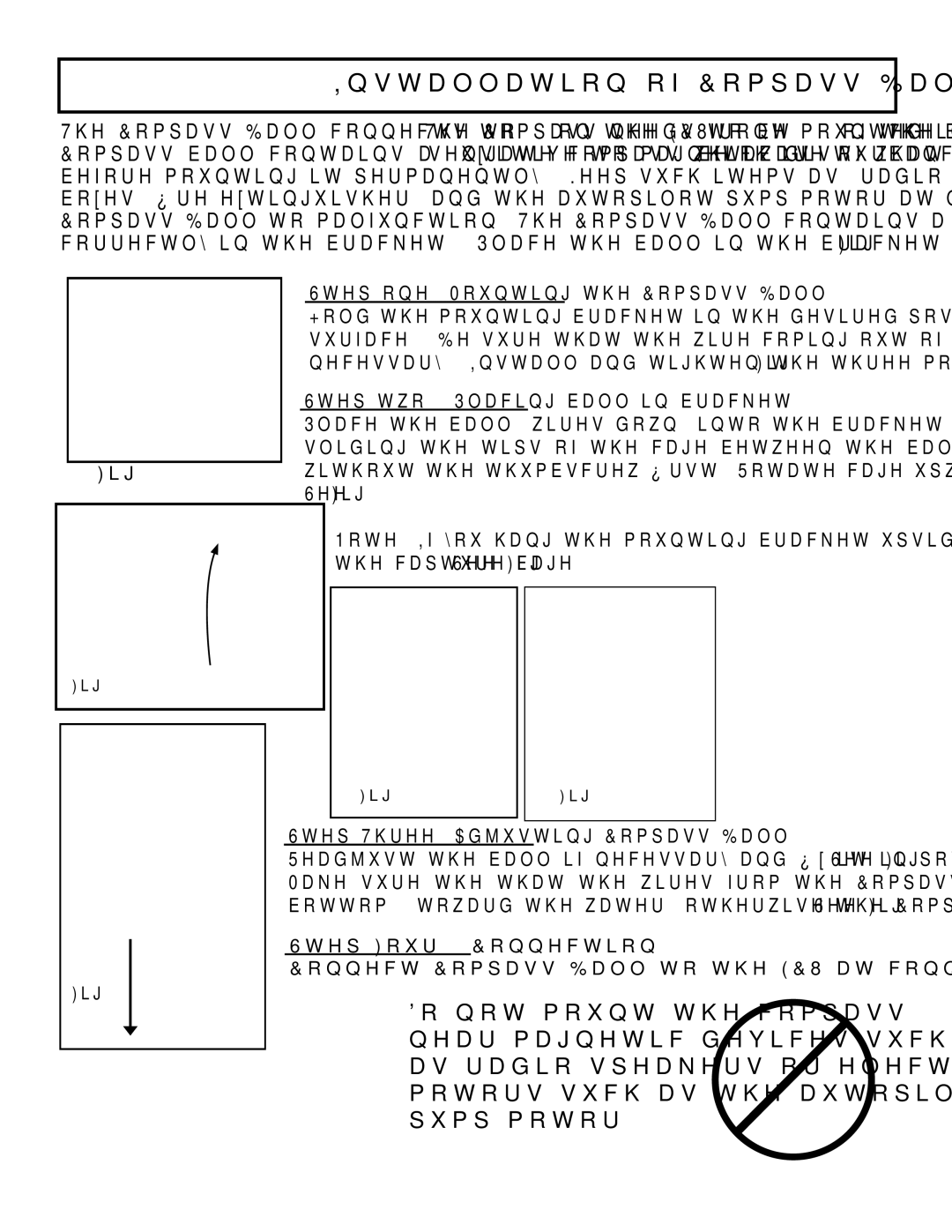
Step one: Mounting the Compass Ball
Hold the mounting bracket in the desired position and drill through the holes into the mounting surface. (Be sure that the wire coming out of the ball can exit the ball straight down.) Tap if necessary. Install and tighten the three mounting screws as shown in Fig. 17.
Step two: Placing ball in bracket
Place the ball, wires down, into the bracket and capture it by snapping the cage over the ball, sliding the tips of the cage between the ball and the legs of the bracket. Do the two legs without the thumbscrew first. Rotate cage upwards to catch the bracket with the thumbscrew.
See Fig. 14.
Note: If you hang the mounting bracket upside down, be sure to run the cable through the capture cage. See Fig. 15
Fig. 15 | Fig. 16 |
Step Three: Adjusting Compass Ball
Readjust the ball if necessary and fix it in position by tightening the thumbscrew. See Fig.16.
Make sure the that the wires from the Compass Ball are pointing straight down, out the bottom; (toward the water) otherwise the Compass Ball will not work properly. See Fig. 17.
Step Four: Connection
Connect Compass Ball to the ECU at connection #4.
Do not mount the compass near magnetic devices such as radio speakers or electric motors such as the autopilot pump motor.
15