www . GarrettCom . com
Managed Fiber Switch
Installation and User Guide
Hardware
Magnum 6K16V Managed Fiber Switch Hardware
Installation and User Guide
Trademarks
Contacting GarrettCom, Inc
Federal Communications Commission
Radio Frequency Interference Statement
Reorient or relocate the receiving antenna
SPECIFICATIONS
Installation
Introduction
OPERATION
5.0 Introduction - Magnum 6K16V Managed Fiber Switch PM
TROUBLESHOOTING
APPENDIX A WARRANTY INFORMATION
APPENDIX B Internal DC Power Supply Options
6K-SERIES MANAGED FIBER SWITCHES, GIGABIT, 100 AND
QUAD-SERIES FIBER SWITCHES, 100 & 10MBPS, FIBER AND
“OUTDOOR” ETHERNET SWITCH, FOR TEMPERATURE
PERSONAL SWITCHES, 10/100MB
MEDIA CONVERTERS, 10MB AND 100MB SERIES
BRIDGE PORT MODULES BPMS, 4 TYPES, FOR SEGMENT
TRANSCEIVERS, 10MB SERIES MINI-TRANSCEIVERS AND COAX
MODELS
1.0 SPECIFICATIONS 1.1 Technical Specifications
Fiber Multi-mode connector types supported
Performance
Network Standards and Compliance, hardware
Fiber Single-mode connector types
Alarm Relay Contacts
Management Console connector
Power Supply Internal
Per-port jumpers and switches
Agency Approvals
NEBS Test Classification NEBS Compliant
Email sales@GarrettCom.com for details
Magnum Managed Fiber Switch 16 ports max
Configuration Options
MODEL DESCRIPTION
1.2 Ordering Information
fiber ports connector
2.0 Introduction 2.1 Inspecting the Package and Product
2.2 Product Description - Magnum 6K16V Managed Fiber Switch
100Mb, mode, and connector
2.2.1 Eight-port SFF fiber modules 6K8-MTRJ, 6K8-MLC, 100Mb fiber
Fig.2.2.2 SFF Fiber Port Modules 6K8-MTRJ to the left and
6K8-MLC or -SLC below
2.2.2 Eight-Port Copper Module, 6K8-RJ45
4@ RJ-45 + 2@ 100Mb SC
The Magnum Combo
six-port modules are also available
with 4@ MTRJ 100Mb mm SFF
2.2.4 Four-Port 10 Mb and 100Mb mm Fiber ST Modules
2.2.6 Gigabit 1000Mbps port modules
1@ 1000Mb Fiber SC + 2@ 100Mb SC
1@ 1000Mb Fiber SC + 4@10/ 100Mb
2.2.6 Packet Prioritization, 802.1p QOS
2.2.7 Frame Buffering and Flow Control
2.2.8 Managed Network Software MNS-6K for Magnum 6K16V
ftp//ftp.garrettcom.com
2.3 Features and Benefits
„ Managed switching for high performance Ethernet LANs
„ Switching services includes 802.1p QoS packet prioritization
„ Features Fiber-Built-In
Example 1 Magnum 6K16V Switch for a Industrial application
2.4 Applications
Fig. 2.1- The Industrial factory floor application with Magnum 6K16V
Internet
SNMP Monitor
3.0 Installation
3.1 Locating Magnum 6K16V Switches
3.2 Connecting Ethernet Media
3.2.1 Connecting Fiber Optic ST-type, “twist-lock”
3.2.2 Connecting Fiber Optic SC-type, Snap-In
3.2.3 Connecting Single-Mode Fiber Optic
IEEE Standard
3.2.5 Connecting Twisted Pair CAT5E or better, Unshielded or Shielded
Media
3.2.6 Connecting Gigabit Media Using GBICs
3.3 DIN-Rail Mounting
3.3.1 Mounting Dimensions for 6K16V with metal brackets
3.4 Powering the Magnum 6K16V Managed Fiber Switch
3.5 Alarm Contacts for monitoring internal power, and Software Traps
Relay Contacts
3.6 6K16V Port Module 6KPM Installation
3.6.1 Preparation for Installing and Removing 6KPMs
Be sure the power cord is unplugged
and will void the warranty
Caution Be careful not to disturb the power supply
Step 2. Remove Chassis Cover
Figure 3.6.1a Removing the Front panel from the unit
Figure 3.6.1b Magnum 6K16V, Top view without chassis cover
3.6.2 Installing 6KPM Cards in the Magnum 6K16V
Step 3. Remove front panel face plate retaining screws
Figure 3.6.1c Top View - 6KPM retaining screws hold Face Plate
Fig 3.6.2a Granddaughter Board shown separately
Fig. 3.6.2c Daughter Board, top view of
version for 4 copper 10/100 ports
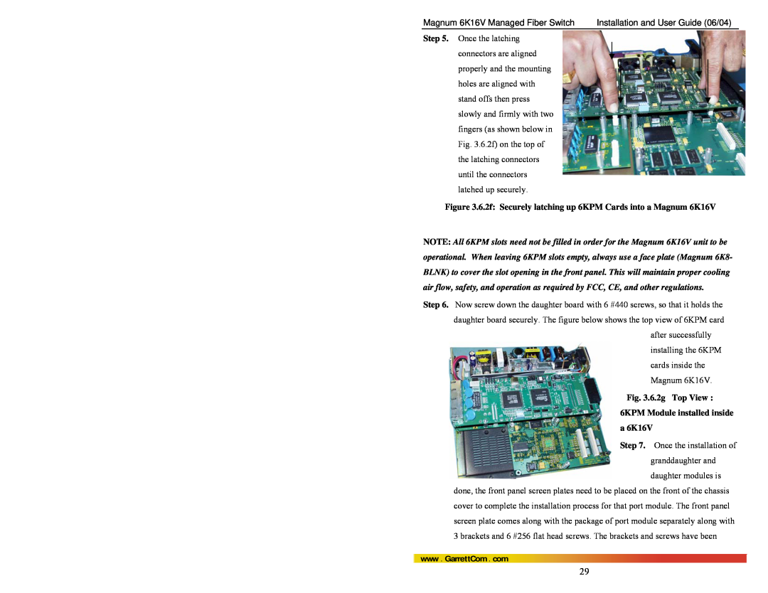
Fig. 3.6.2g Top View 6KPM Module installed inside a 6K16V
Figure 3.6.2f Securely latching up 6KPM Cards into a Magnum 6K16V
Caution Be sure the power cord is unplugged
3.6.3 Removing 6KPM Cards
firmly. Figure 3.6.3a Top View - 6 retaining s crews shown by arrows
Step 3. Remove 6KPM Card
3.7 Connecting a Management Console Terminal to Magnum 6K16V
DB-9 Console port connector
3.7.1 RS-232 DB-9 Console Com port Serial port pin assignments
Enlarged view of Magnum 6K16V Console Port area
4.1 Switching Functionality
4.0 OPERATION
Filtering and Forwarding
Address Learning
4.3 Up-link Manual Switches set as = , for RJ-45 port only
Power LED, ON when external power is applied to the unit
Full / Half duplex LED, ON when the port is running full
Speed LED, ON when the speed is 100Mbps , OFF when the
Auto-negotiation per-port for 802.3u-compliant switches occurs when
4.6 Power Budget Calculations for Magnum 6K16V PM’s with Fiber Media
4.5 Flow-control, IEEE 802.3x standard
LXSC40 and the “Cable Loss” for 9/125 Single-mode is 0.2 dB/km LXSC70
Magnum 6K16V Managed Fiber Switch
Installation and User Guide 06/04
6KP4V
Km, fdx
5.0 Introduction - Magnum 6K16V Managed Fiber Switch Port Modules
5.1 Inspecting the Package and Product
5.2 6KPM Module Description
5.2.1b 6KP4-F10ST, 4@10Mb multi-mode FX-ST “twist lock” Module
ports are ST connectors
and configured as 10Mb
Half-duplex by default
connectors and configured
mode SC-type connectors. It
module of the 6K16V Switch
The Magnum 6KP6
RJMSC is also a Combo 6 Port
as 25+ Km see Power Budget, Section
“small-form-factor”
5.2.5 6KP8-MTRJ, 8 @100Mb multi-mode FX , MTRJ Small-Form-factor
The functionality of this 100BASE-FX multi-mode 4 port module is
6KP8-MTRJ
MTRJ connectors give an advantage
5.2.6 6KP8-45MT, 4@ 10/100Mbps RJ-45 and 4@100Mb multi-mode FX
MTRJ Small-Form-Factor
The Magnum 6KP8-45MT
5.2.9 6KP8-RJ45 Twisted Pair, 10/100Mb 8-Port
connecting to a hub or another switch
5.2.11 GBIC-SXSC Gigabit fiber1000Mb, multi-mode SC Connector
6KP8V
Single-Mode Fiber port LC
5.2.11a GBIC-LXSC Gigabit fiber 1000Mb, multi-mode SC Connector
5.2.12 6KM-BLNK
6.0 TROUBLESHOOTING
6.1 Before Calling for Assistance
6.2 When Calling for Assistance
6.3 Return Material Authorization RMA Procedure
No Problem Found
GarrettCom, Inc 213 Hammond Ave Fremont, CA Attn. Customer Service
6.4 Shipping and Packaging Information
B1.0 SPECIFICATIONS FOR MAGNUM 6K16V SWITCHES, DC POWER
B2.0 -48VDC, 24VDC and 125VDC POWER, THEORY OF OPERATION
B3.0 APPLICATIONS FOR DC POWERED ETHERNET SWITCHES
B4.0 6K16V’S -48V, 24, 125 OR 5VDC INSTALLATION
B4.1 UL Requirements for DC-powered units
B7.0 TROUBLESHOOTING
hooked up at the last
B5.0 OPERATION
Power Supply Internal, 24VDC Dual-Source, model # Dual-Src-24V
Power Supply Internal, 125VDC Dual-Source, model # Dual-Src-125V
C3.0 DUAL-SOURCE OPTION, THEORY OF OPERATION
C4.0 FEATURES AND BENEFITS OF THE DUAL-SOURCE DESIGN
C5.0 INSTALLATION
C5.1 UL Requirements
C6.0 ORDERING INFORMATION
Example Magnum 6K16VR-48VDC
C7.0 OPERATION