GBC 3064WF
A
B
![]() C
C
Figure 2
B |
A |
C |
Figure 3
![]() D
D
B
F
![]() E
E
C
Figure 4
Operation Manual
Media Tables: (Fig. 2C & 3C)
On both the Front Media & Rear Media tables, the safety interlock switch will not allow the Laminator to operate at full speed unless the tables are properly installed.
The Media tables are used to position items for Lamination. There are two media tables on the machine one on the front & one on the rear of the Laminator. The Front Media table incorporates an Idler on the leading edge of the table. This is used for roll to roll applications during lamination
Note:
The Laminator will operate only when the Media Table and Media Table Latch are Properly Installed.
The Accessories Include:
1.Straight Slitter: Used for slitting the media after lamination
2.Feed Guide: Used for guiding Media through the laminator (Fig. 2B)
3.Pressure Plate: Used for guiding stock and ensuring a wrinkle free feed into the roller Nip. (Fig 2A)
Rewind Take up: (Fig. 3 – Item A)
This machine has one dedicated rewind film take up positioned on the lower back of the machine
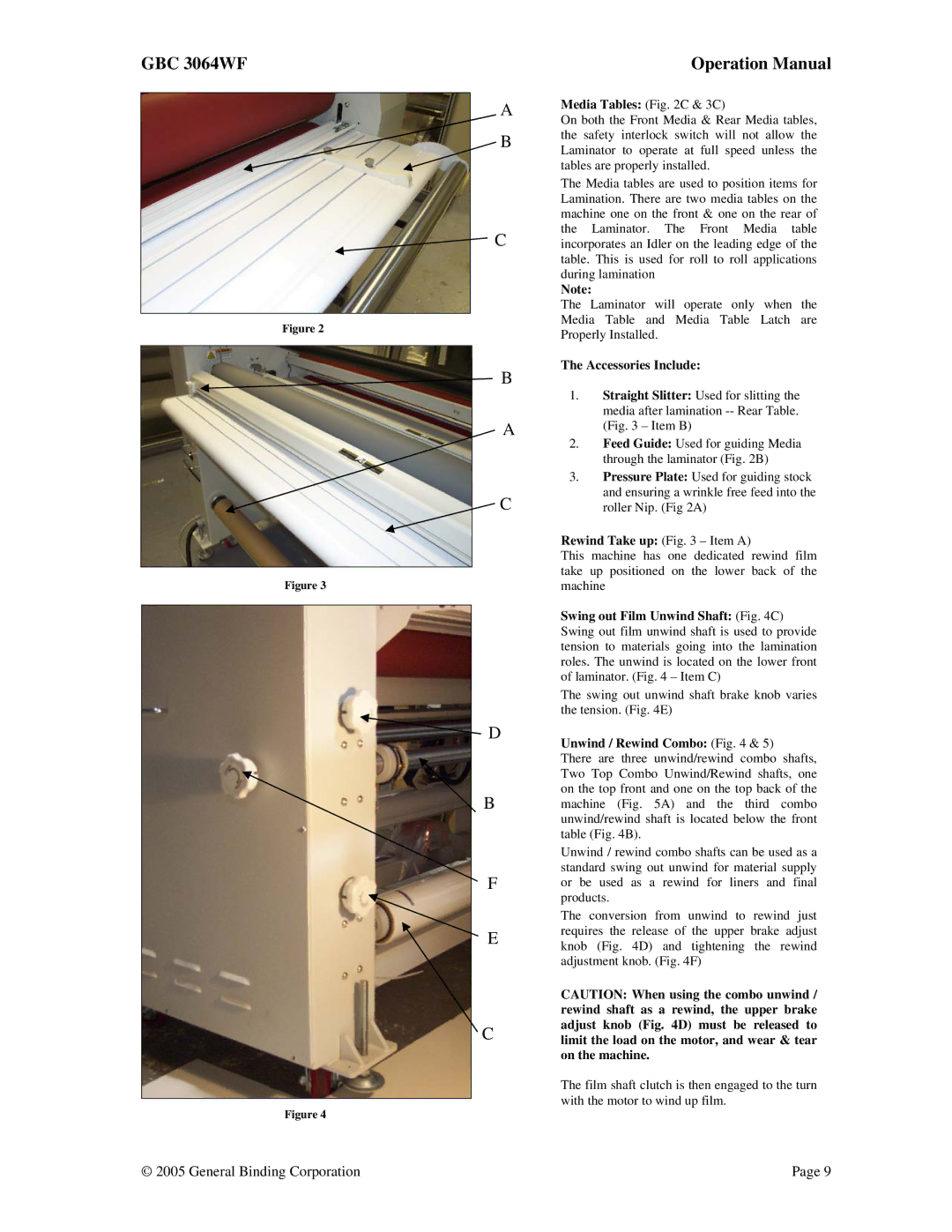
Swing out Film Unwind Shaft: (Fig. 4C) Swing out film unwind shaft is used to provide tension to materials going into the lamination roles. The unwind is located on the lower front of laminator. (Fig. 4 – Item C)
The swing out unwind shaft brake knob varies the tension. (Fig. 4E)
Unwind / Rewind Combo: (Fig. 4 & 5)
There are three unwind/rewind combo shafts, Two Top Combo Unwind/Rewind shafts, one on the top front and one on the top back of the machine (Fig. 5A) and the third combo unwind/rewind shaft is located below the front table (Fig. 4B).
Unwind / rewind combo shafts can be used as a standard swing out unwind for material supply or be used as a rewind for liners and final products.
The conversion from unwind to rewind just requires the release of the upper brake adjust knob (Fig. 4D) and tightening the rewind adjustment knob. (Fig. 4F)
CAUTION: When using the combo unwind / rewind shaft as a rewind, the upper brake adjust knob (Fig. 4D) must be released to limit the load on the motor, and wear & tear on the machine.
The film shaft clutch is then engaged to the turn with the motor to wind up film.
© 2005 General Binding Corporation | Page 9 |