GBC 3064WF | Operation Manual |
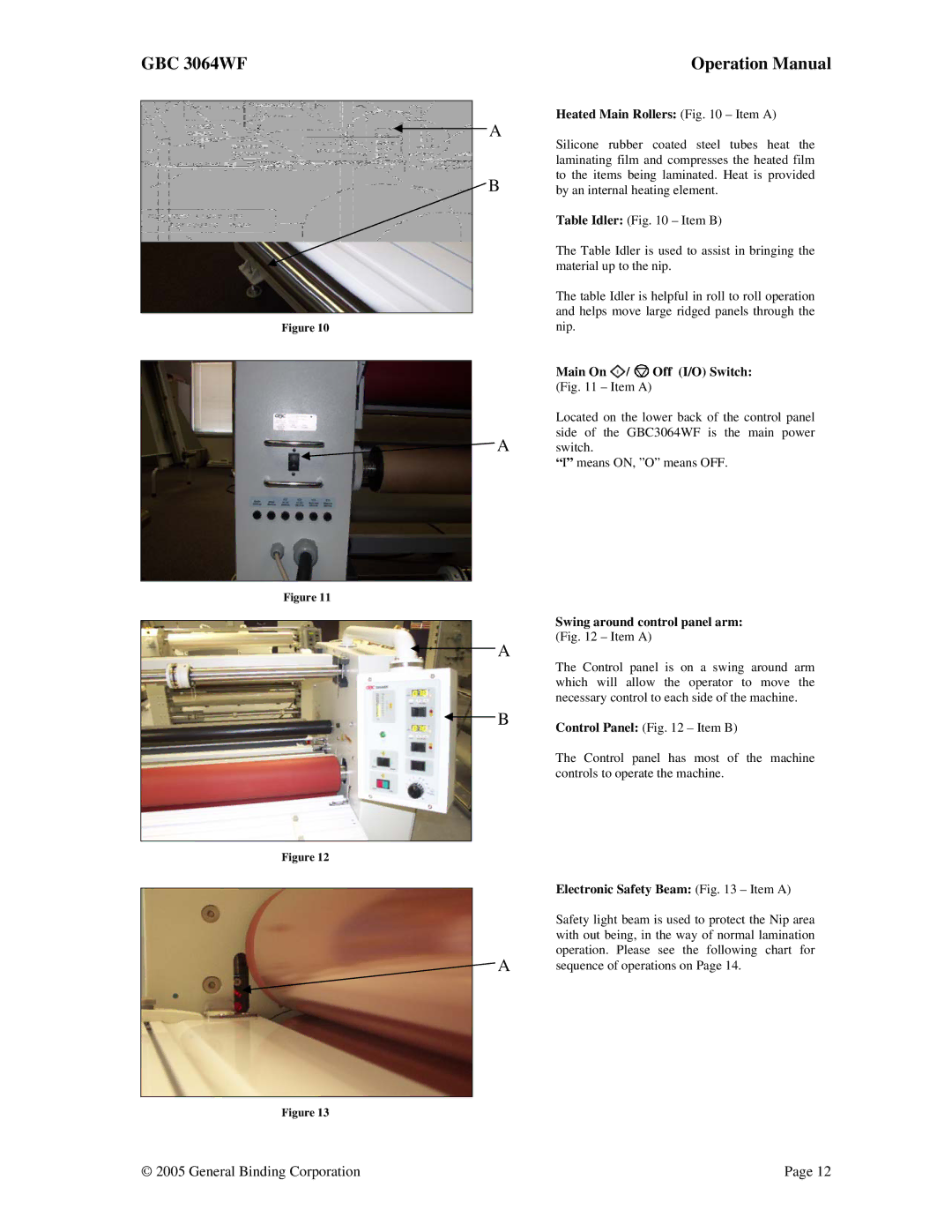
Figure 10
A | Heated Main Rollers: (Fig. 10 – Item A) | |||
Silicone rubber coated steel tubes heat the | ||||
| ||||
| laminating film and compresses the heated film | |||
B | to the items being laminated. Heat is provided | |||
by an internal heating element. | ||||
| Table Idler: (Fig. 10 – Item B) | |||
| The Table Idler is used to assist in bringing the | |||
| material up to the nip. | |||
| The table Idler is helpful in roll to roll operation | |||
| and helps move large ridged panels through the | |||
| nip. |
|
| |
| Main On | / | Off (I/O) Switch: | |
| (Fig. 11 – Item A) |
| ||
| Located on the lower back of the control panel | |||
A | side of the GBC3064WF is the main power | |||
switch. |
|
| ||
“I” means ON, ”O” means OFF.
Figure 11
A
Swing around control panel arm: (Fig. 12 – Item A)
The Control panel is on a swing around arm which will allow the operator to move the necessary control to each side of the machine.
BControl Panel: (Fig. 12 – Item B)
The Control panel has most of the machine controls to operate the machine.
Figure 12
| Electronic Safety Beam: (Fig. 13 – Item A) |
| Safety light beam is used to protect the Nip area |
| with out being, in the way of normal lamination |
A | operation. Please see the following chart for |
sequence of operations on Page 14. |
Figure 13
© 2005 General Binding Corporation | Page 12 |
