Installation Instructions

INSTALLING THE REFRIGERATOR

REFRIGERATOR LOCATION

Do not install the refrigerator where the temperature will go below 60°F (16°C) because it will not run often enough to maintain proper temperatures.

Do not install the refrigerator where the temperature will go above 100°F (37°C) because it will not perform properly.

Install it on a floor strong enough to support it fully loaded.

CLEARANCES

Allow the following clearances for ease of installation, proper air circulation and plumbing and electrical connections.


Standard Depth


Models

Sides

1/8(3 mm)

Top

1(25 mm)

Back

1(25 mm)

REMOVETOP CAP (on some models)

•IMPORTANT NOTE: This refrigerator is 34-1/2deep.

Doors and passageways leading to the installation location must be at least 36wide in order to leave the doors and handles attached to the refrigerator while transporting it into the installation location. If passageways are less than 36, the refrigerator doors and handles can easily be scratched and damaged. The top cap and doors can be removed to allow the refrigerator to be safely moved indoors. Start with Step A.

•If it is not necessary to remove doors, skip Step A. Leave tape and all packaging on doors until the refrigerator is in the final location.

•SKID REMOVAL: Tilt refrigerator to each side to remove skid.

•NOTE: Use a padded hand truck to move this refrigerator. Place the refrigerator on the hand truck with a side against the truck. We strongly recommend that TWO PEOPLE move and complete this installation.

ALocate and remove the two Phillips head screws on the top of the refrigerator. Remove the two screws on each side at the rear of the top cap. Lift off and remove top cap.

BRemove the fresh-food door(s). Refer to Steps 1 and 3 of “Reversing the Door Swing” section or Steps 1 and 2 of “Removing the Doors” section.

CRemove the bottom freezer drawer or door. Refer to “Removing Freezer Drawer” section or Step 2 of “Reversing the Door Swing” section.

DMove refrigerator to the installation location.

REMOVETOP CAP (cont.) (on some models)

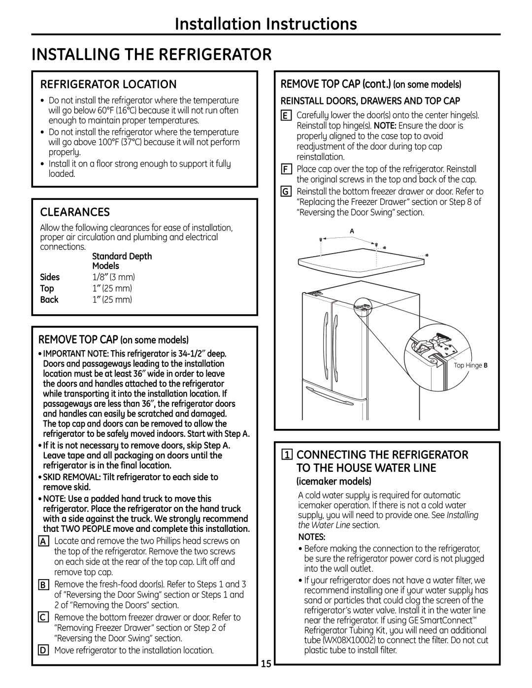
REINSTALL DOORS, DRAWERS AND TOP CAP

ECarefully lower the door(s) onto the center hinge(s). Reinstall top hinge(s). NOTE: Ensure the door is properly aligned to the case top to avoid readjustment of the door during top cap reinstallation.

FPlace cap over the top of the refrigerator. Reinstall the original screws in the top and back of the cap.

GReinstall the bottom freezer drawer or door. Refer to “Replacing the Freezer Drawer” section or Step 8 of “Reversing the Door Swing” section.

A

Top Hinge B

1CONNECTING THE REFRIGERATOR TO THE HOUSE WATER LINE

(icemaker models)

A cold water supply is required for automatic icemaker operation. If there is not a cold water supply, you will need to provide one. See Installing the Water Line section.

NOTES:

Before making the connection to the refrigerator, be sure the refrigerator power cord is not plugged into the wall outlet.

If your refrigerator does not have a water filter, we recommend installing one if your water supply has sand or particles that could clog the screen of the refrigerator’s water valve. Install it in the water line near the refrigerator. If using GE SmartConnectRefrigerator Tubing Kit, you will need an additional tube (WX08X10002) to connect the filter. Do not cut plastic tube to install filter.

15

Page 15
Image 15
GE 200D9366P004 operating instructions Refrigerator Location, Clearances, Removetop CAP cont. on some models

200D9366P004 specifications

The GE 200D9366P004 is a high-performance component designed for various industrial applications, particularly in power generation and distribution systems. This device is a part of General Electric’s extensive lineup of electrical components, renowned for their durability and operational efficiency.

One of the main features of the GE 200D9366P004 is its robust design capacity, built to handle significant electrical loads while maintaining stability and safety. The component is engineered to comply with rigorous industry standards, ensuring not only reliability but also longevity in harsh operational environments. This makes it suitable for a range of applications, from power plants to critical infrastructure systems.

In terms of technologies, the GE 200D9366P004 incorporates advanced electric and electronic control systems that enhance its operational capabilities. This includes state-of-the-art monitoring technologies that provide real-time data on performance metrics, allowing for prompt detection of anomalies and facilitating proactive maintenance strategies. This predictive capability is crucial in minimizing downtime and extending the lifecycle of the equipment.

The operating characteristics of the GE 200D9366P004 are particularly noteworthy. It is designed for optimal thermal performance, ensuring that heat dissipation is managed efficiently. This helps in maintaining consistent performance even under high operational loads. Additionally, the component features advanced insulating materials that contribute to its reliability and efficiency, reducing the risks associated with electrical failures.

Another notable characteristic is its modular design, which simplifies installation and maintenance processes. This modularity allows for easier upgrades and repairs, making it a flexible choice for many organizations looking to enhance their operational efficiency without extensive downtime.

Overall, the GE 200D9366P004 stands out in the industrial landscape for its combination of advanced technology, rugged reliability, and operational efficiency. Whether utilized in power generation, industrial automation, or management of critical electrical infrastructure, this component exemplifies GE’s commitment to quality and innovation in electrical solutions, making it a preferred choice for professionals aiming to achieve high-performance standards in their operations.