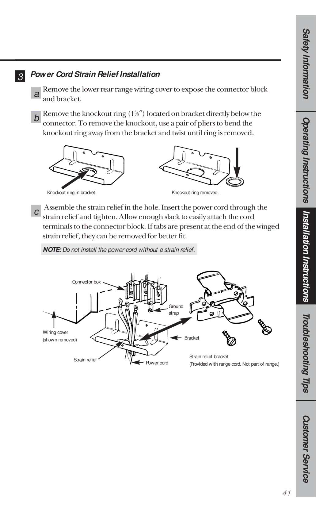
3 Power Cord Strain Relief Installation
| Remove the lower rear range wiring cover to expose the connector block |
a | |
| and bracket. |
| Remove the knockout ring (13⁄8″) located on bracket directly below the |
b | |
| connector. To remove the knockout, use a pair of pliers to bend the |
| knockout ring away from the bracket and twist until ring is removed. |
| Knockout ring in bracket. | Knockout ring removed. | |
| Assemble the strain relief in the hole. Insert the power cord through the | ||
c | |||
| strain relief and tighten. Allow enough slack to easily attach the cord | ||
| terminals to the connector block. If tabs are present at the end of the winged | ||
| strain relief, they can be removed for better fit. | ||
|
| ||
| NOTE: Do not install the power cord without a strain relief. |
| |
|
|
|
|
| Connector box |
|
|
|
|
|
|
|
|
| Ground | ||
|
|
|
| strap | ||
|
|
|
|
|
| |
|
|
|
|
|
|
|
Wiring cover |
|
|
|
| Bracket | |
(shown removed) |
|
|
|
| ||
|
|
|
| |||
|
|
|
|
| ||
| Strain relief |
| Power cord |
|
| Strain relief bracket |
|
|
|
| (Provided with range cord. Not part of range.) | ||
|
|
|
|
| ||
Safety Information Operating Instructions Installation Instructions Troubleshooting Tips Customer Service
41