Manuals
/
GE
/
Household Appliance
/
Water System
GE
6000A Step-by-step installation instructions, B, Customer Service, Install bypass valve
Models:
6000A
1
7
28
28
Download
28 pages
45.09 Kb
4
5
6
7
8
9
10
11
Troubleshooting
Specs
Install
Parts list
Error codes
Regeneration Chart
Program the Timer
Problem
Parts and Accessories
How to
Page 7
Image 7
Page 6
Page 8
Page 7
Image 7
Page 6
Page 8
Contents
Installation and Owner’s Manual
GE Answer Center
GXSS17Z01
Part No. 215C1044P003-1 Pub. No. 49-50007-1 8-98 CG
Installation Instructions
CustomerService
Troubleshooting Tips
Customer Service
Read and follow this Safety Information carefully
IMPORTANT SAFETY INFORMATION READ ALL INSTRUCTIONS BEFORE USING
SAFETY PRECAUTIONS
PROPER INSTALLATION
See Where to Install the Softener section for more details
Installation instructions
Important Installation Recommendations
Unpacking and Inspection
Tools and Materials Required for Installation
Customer Service
Plan How You Will Install the Softener
Where to Install the Softener
Typical Installation Illustration
SafetyInstructions
Operating Instructions Installation Instructions
TroubleshootingTips
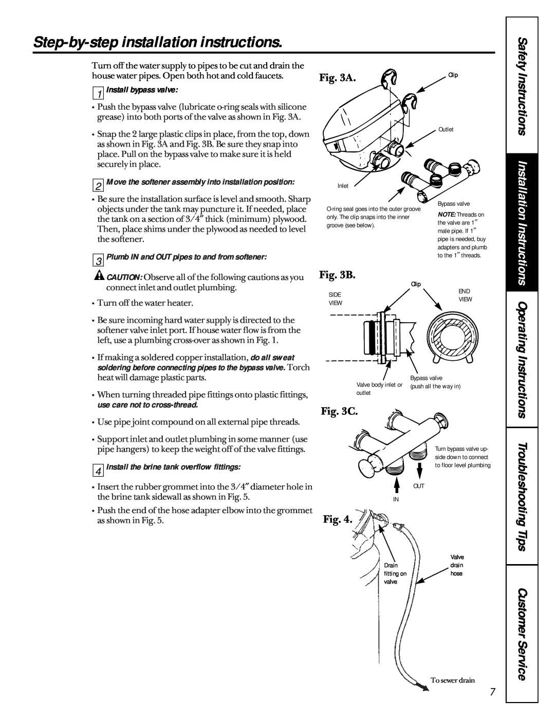
Fig. 3C
Step-by-step installation instructions
Fig. 3A
Fig. 3B
5 Connect and run the valve drain hose
Fig. 4A
Install grounding clamps and wire
installation for water leaks
10 Connect to electrical power
Troubleshooting Tips Customer Service
Safety Instructions Installation
Instructions Operating Instructions
Set the timer
Solid State Timer
CustomerService
Program the Timer
Instructions Troubleshooting Tips
Safety Instructions Installation Instructions Operating
Specifications/Dimensions
Fill
Service
About the water softener system
Automatic Hard Water Bypass During Regeneration
bridge
Breaking a Salt Bridge
only. Do not over-tighten the cap or housing
Cleaning the Nozzle and Venturi Assembly
What to do When a Power Outage Occurs
About the face plate timer features
Troubleshooting Tips
Error Code
TroubleshootingTips Operating Instructions
Installation Instructions SafetyInstructions
Setting the Timer for Days and Fill Minutes of Regeneration
About regenerating the system
Pounds of Salt Used Each Regeneration
Regeneration Chart
If you need help to program the timer, all the GE Answer Center
Water Hardness-Grains Per Gallon
What To Do
Before you call for service…
Problem
Possible Causes
What Brand
GE Service Protection Plus
Warranty Registration Department P.O. Box Louisville, KY
General Electric Company
Consumer Product Ownership Registration
Dear Customer
Model Number
Serial Number
Customer Service
Parts list
Parts catalog
Parts list
Parts catalog
Operating Instructions
Troubleshooting Tips
Safety Instructions
Installation Instructions
Operating Instructions
TroubleshootingTips
What GE Will Not Cover
GE Water Softening System Warranty
Safety Instructions Installation Instructions
GE Will Replace, At No Charge To You
Parts and Accessories
Service Telephone Numbers
Special Needs Service
Service Contracts
Top
Page
Image
Contents