MX150 User Setup - SET Menu
| S1 | OK |
01: 50 | ||
| FRI 31 MAY 2003 | |
MORE | TEST | |
|
| |
|
|
|
1 VAB = ___ | 2 VAB = ___ | |
VBC = ___ |
| |
VCA = ___ |
| |
MORE CFG | SET ESC | |
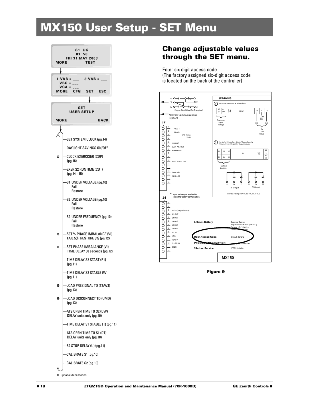
Change adjustable values through the SET menu.
Enter six digit access code
(The factory assigned
S E T
USER SETUP
41
52
63
Engine Start Relay
Network Communications (Option)
WARNING
1Controller Inputs must be relay Isolated.
A2 | A1 | RELAY | 14 | 11 | 12 | |
(+) | ||||||
|
|
| ||||
|
|
|
|
|
|
COM
MOREBACK
Customer
J2
*
1
PROG 1
2
PROG 2
3GRD (Input
InputN.O N.C Voltage
To
J2/J4
Inputs
4
Sink)
5
6
7
8
9
NIA OUT
ELEV. PRE. OUT
ALARM OUT
2Controller Outputs have "Limited" Source Capacity. Use only GE
11 | 14 | 12 |
| A1 |
| (+) | |||
|
|
| R1 | |
21 | 24 | 22 |
| A2 |
| ||||
|
|
|
|
10
11
12
13
14
15
16
MOTOR DISC. OUT
INHIB.>S1
INHIB.>S2
Output |
|
|
|
|
|
Contacts |
|
|
|
|
|
11 | 14 | 12 | 21 | 24 | 22 |
| R1 Output |
|
| R1 Output |
|
 Optional Accessories
* | Contact Rating: 10A @ 250 VAC or 30 VDC |
J4
*1
2
3+12v (Output Source)
4LN OUT
5L4 OUT
6 | L3 OUT | Lithium Battery | Exerciser Battery | |
| ||||
7 | L2 OUT |
| ||
8 | L1 OUT |
| Service | |
| During normal operation | |||
9 | YN IN |
|
| |
10 | YE IN | User Access Code | ||
11 | TSNL IN | |||
|
| |||
12 | Q2/TSL IN | PRODUCT INFORMATION | www.geindustrial.com | |
13 | S12 IN | |||
14 |
| |||
|
|
|
MX150
Figure 9
■ 18 | ZTG/ZTGD Operation and Maintenance Manual | GE Zenith Controls ■ |