Manuals
/
GE
/
Computer Equipment
/
Switch
GE
70R-1000D
manual
GE Zenith Controls
Models:
70R-1000D
1
1
36
36
Download
36 pages
4.76 Kb
1
2
3
4
5
6
7
8
Troubleshooting
Install
CDT One Event Timer Exerciser
Maintenance
Optional Accessories
MX150 User Setup CFG Menu
Testing
Power Connections
Page 1
Image 1
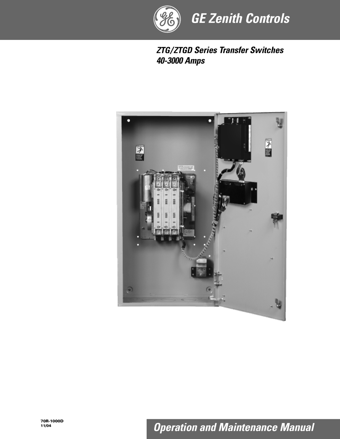
GE Zenith Controls
ZTG
/
ZTGD
Series Transfer Switches
40-3000
Amps
70R-1000D
11/04
Operation and Maintenance Manual
Page 1
Page 2
Page 1
Image 1
Page 1
Page 2
Contents
GE Zenith Controls
Table of Contents
Authorized Service
Introduction
Equipment Inspection and Storage
Safety / Installation
Final Equipment Inspection
Mounting
Power Connections
Installation cont’d
Engine Start Control Connections
Installation cont’d
Initial Energization
GE Zenith Controls
R E T E S T
Initial Energization cont’d
MX150 Controller
MX150 Microprocessor Controller
LCD & Keypad
MX150 Microprocessor Controller cont’d
Standard Features, Mstdg Option Pkg
User Setting for Voltage & Frequency
Source
Calibrate
R50
Std. Features, Mstdg Option Pkg. cont’d
S13
CDP replaces CDT
Standard Features, Mexeg Option Pkg
Optional Accessories
CDT One Event Timer Exerciser
How to Set the System Clock
How to Bypass Cancel an exercise during an exercise cycle
CDT One Event Timer Exerciser cont’d
Load / No-Load Clock Exerciser
CDP Clock Exerciser
Turn options on or OFF via keypad through the CFG menu
MX150 User Setup CFG Menu
Change adjustable values through the SET menu
MX150 User Setup SET Menu
View System Data
MX150 User Setup System Info
ATS Testing
Testing
Delayed Transition
Standard Transition
Sequence of Operation
Timer Designations as they appear in the SET menu
Standard and Delay Transition
Controls Power Supply CPS
Standard Transition CPS Schematic
Controls Power Supply CPS cont’d
Delayed Transition CPS Schematic
General Troubleshooting
Troubleshooting and Diagnostics
Inspection and Cleaning
Maintenance and Testing
Testing
Servicing
Standard Transition 40 to 260 Amps Solenoid Type
Power Panel and Replacement Parts
Standard Transition 400 to 600 Amps Molded Type
Power Panel and Replacement Parts cont’d
ARC Grid Removed for Clarity
Standard Transition 800 to 1200 Amps
Stationary Contact Moveable Contact
Standard Transition 1600 to 3000 Amps
Amps
Delayed Transition 40 to 600 Amps
SCR-EO Movable Contact Stationary Contact
Delayed Transition 800 to 1200 Amps
Movable E3 Contact Stationary
Delayed Transition 1600 to 3000 Amps
Page
Page
Page
GE Zenith Controls
Top
Page
Image
Contents