Installation (cont’d)
Initial Energization (cont’d)
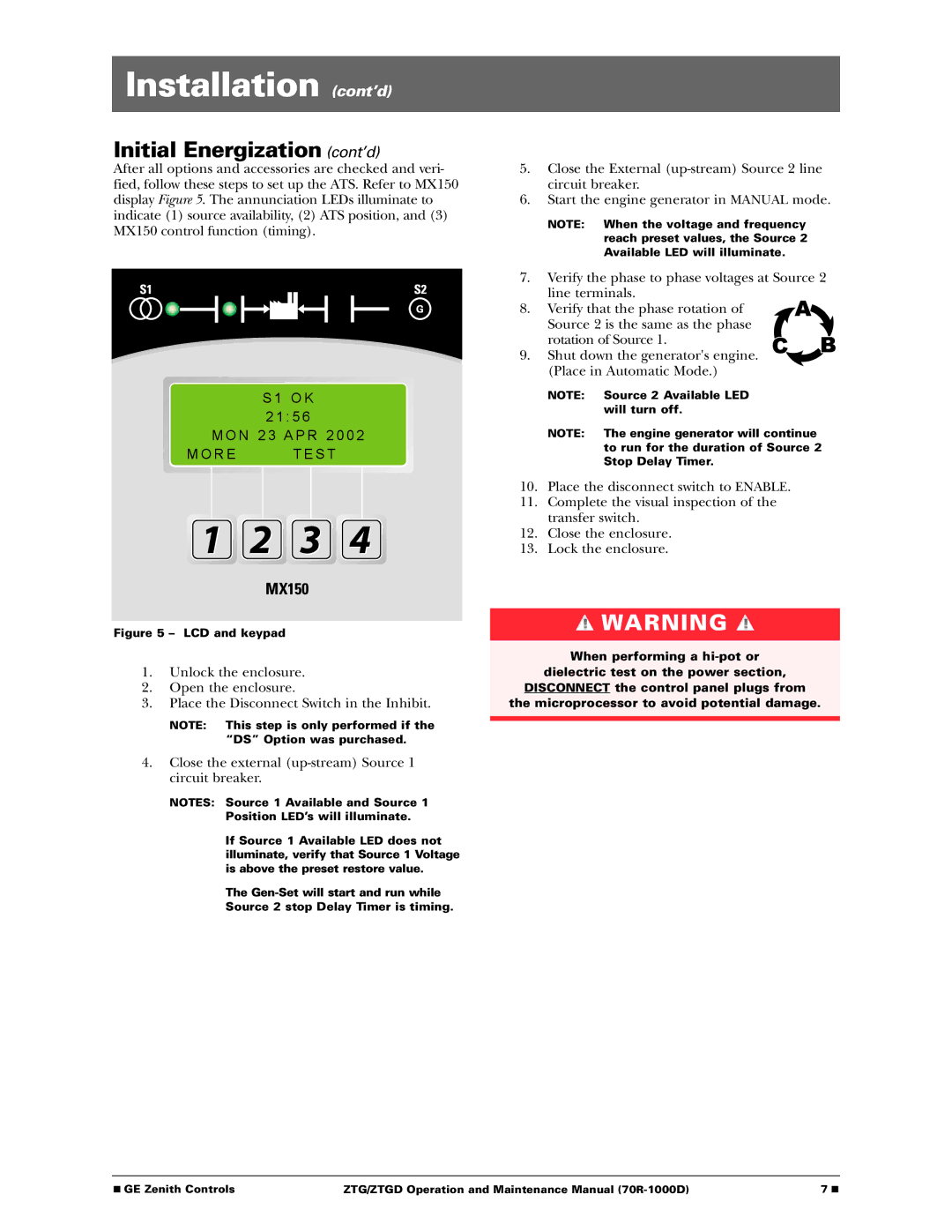
After all options and accessories are checked and veri- fied, follow these steps to set up the ATS. Refer to MX150 display Figure 5. The annunciation LEDs illuminate to indicate (1) source availability, (2) ATS position, and (3) MX150 control function (timing).
S 1 O K
2 1 : 5 6
M O N 2 3 A P R 2 0 0 2
M O R E T E S T
Figure 5 – LCD and keypad
1.Unlock the enclosure.
2.Open the enclosure.
3.Place the Disconnect Switch in the Inhibit.
NOTE: This step is only performed if the “DS” Option was purchased.
4.Close the external
NOTES: Source 1 Available and Source 1
Position LED’s will illuminate.
If Source 1 Available LED does not illuminate, verify that Source 1 Voltage is above the preset restore value.
The
Source 2 stop Delay Timer is timing.
5.Close the External
6.Start the engine generator in MANUAL mode.
NOTE: When the voltage and frequency reach preset values, the Source 2 Available LED will illuminate.
7.Verify the phase to phase voltages at Source 2
line terminals.
8. Verify that the phase rotation of Source 2 is the same as the phase rotation of Source 1.
9. Shut down the generator's engine. (Place in Automatic Mode.)
NOTE: Source 2 Available LED will turn off.
NOTE: The engine generator will continue to run for the duration of Source 2 Stop Delay Timer.
10.Place the disconnect switch to ENABLE.
11.Complete the visual inspection of the transfer switch.
12.Close the enclosure.
13.Lock the enclosure.
![]() WARNING
WARNING ![]()
When performing a
dielectric test on the power section,
DISCONNECT the control panel plugs from
the microprocessor to avoid potential damage.
■ GE Zenith Controls | ZTG/ZTGD Operation and Maintenance Manual | 7 ■ |
