Installation (cont’d)
![]() DANGER
DANGER ![]()
HAZARDOUS VOLTAGE
(Can Cause Severe Injury or Death)
Turn OFF all power before installation, adjustment, or removal of transfer switch or any of its components.
Power Connections
GE Zenith transfer switches are supplied with UL listed solderless screw type terminals as standard for the Source 1, Source 2 and Load power connections.
Table 1 lists the number and sizes of cable lugs supplied as standard for each switch amp rating.
Connect the Source 1, Source 2, and Load conductors to the clearly marked terminals on the transfer switch. Remove surface oxides from cables by cleaning with a wire brush. Verify that all connections are correct before tightening the lugs. All cable lug connections must be tightened to the proper torque values as shown in Table 2.
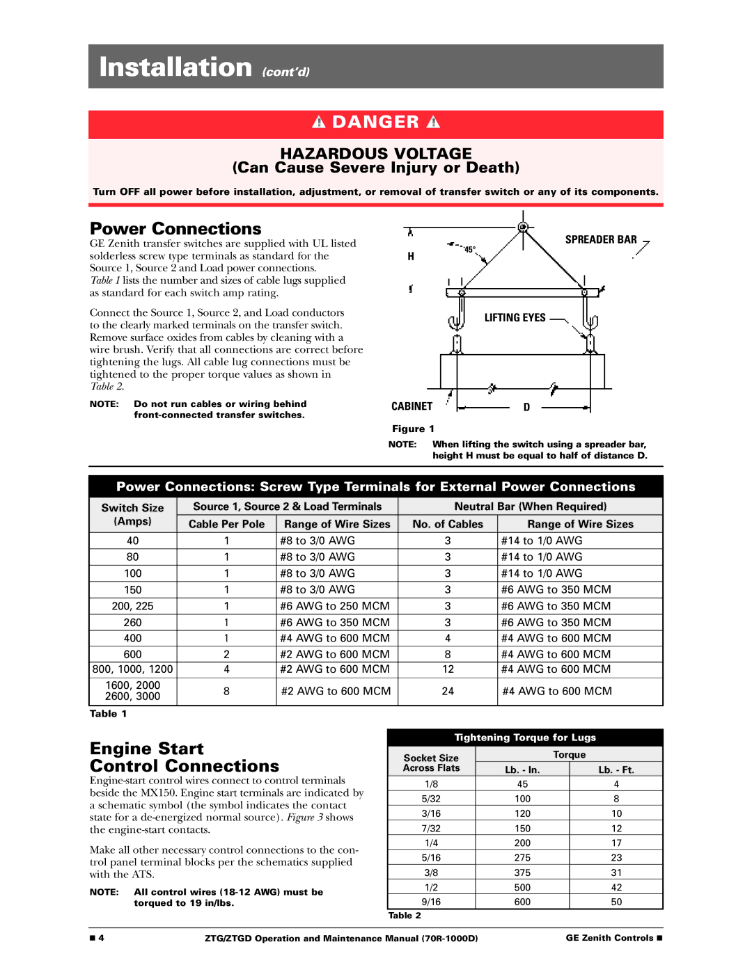
H
SPREADER BAR
45°
LIFTING EYES
NOTE: Do not run cables or wiring behind
CABINETD
Figure 1
NOTE: When lifting the switch using a spreader bar, height H must be equal to half of distance D.
Power Connections: Screw Type Terminals for External Power Connections
Switch Size | Source 1, Source 2 & Load Terminals | Neutral Bar (When Required) | |||
(Amps) | Cable Per Pole | Range of Wire Sizes | No. of Cables | Range of Wire Sizes | |
40 | 1 | #8 to 3/0 AWG | 3 | #14 to 1/0 AWG | |
|
|
|
|
| |
80 | 1 | #8 to 3/0 AWG | 3 | #14 to 1/0 AWG | |
|
|
|
|
| |
100 | 1 | #8 to 3/0 AWG | 3 | #14 to 1/0 AWG | |
150 | 1 | #8 to 3/0 AWG | 3 | #6 AWG to 350 MCM | |
200, 225 | 1 | #6 AWG to 250 MCM | 3 | #6 AWG to 350 MCM | |
|
|
|
|
| |
260 | 1 | #6 AWG to 350 MCM | 3 | #6 AWG to 350 MCM | |
|
|
|
|
| |
400 | 1 | #4 AWG to 600 MCM | 4 | #4 AWG to 600 MCM | |
|
|
|
|
| |
600 | 2 | #2 AWG to 600 MCM | 8 | #4 AWG to 600 MCM | |
800, 1000, 1200 | 4 | #2 AWG to 600 MCM | 12 | #4 AWG to 600 MCM | |
|
|
|
|
| |
1600, 2000 | 8 | #2 AWG to 600 MCM | 24 | #4 AWG to 600 MCM | |
2600, 3000 | |||||
|
|
|
| ||
Table 1
Engine Start
Control Connections
Make all other necessary control connections to the con- trol panel terminal blocks per the schematics supplied with the ATS.
NOTE: All control wires
Tightening Torque for Lugs
Socket Size |
| Torque | |
Across Flats | Lb. - In. |
| Lb. - Ft. |
1/8 | 45 |
| 4 |
5/32 | 100 |
| 8 |
3/16 | 120 |
| 10 |
7/32 | 150 |
| 12 |
1/4 | 200 |
| 17 |
5/16 | 275 |
| 23 |
3/8 | 375 |
| 31 |
1/2 | 500 |
| 42 |
9/16 | 600 |
| 50 |
Table 2
■ 4 | ZTG/ZTGD Operation and Maintenance Manual | GE Zenith Controls ■ |